Toyota Tacoma (2015-2018) Service Manual: Removal
REMOVAL
CAUTION / NOTICE / HINT
NOTICE:
Release the vacuum from booster by depressing the brake pedal several times.
Then remove the brake master cylinder from brake booster.
PROCEDURE
1. PRECAUTION
NOTICE:
After turning the ignition switch off, waiting time may be required before disconnecting the cable from the negative (-) battery terminal. Therefore, make sure to read the disconnecting the cable from the negative (-) battery terminal notices before proceeding with work.
Click here .gif)
2. DISCONNECT CABLE FROM NEGATIVE BATTERY TERMINAL
NOTICE:
When disconnecting the cable, some systems need to be initialized after the cable is reconnected.
Click here
3. REMOVE LOWER NO. 1 INSTRUMENT PANEL AIRBAG ASSEMBLY
Click here
4. REMOVE BRAKE MASTER CYLINDER SUB-ASSEMBLY
Click here
5. SEPARATE MASTER CYLINDER PUSH ROD CLEVIS
Click here
6. REMOVE BRAKE BOOSTER ASSEMBLY
|
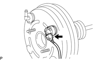
(a) Disconnect the vacuum warning switch assembly connector. (for 2GR-FKS) |
|
|
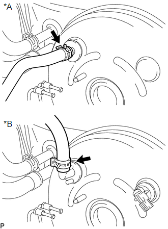
(b) Disconnect the vacuum hose from the brake booster assembly. Text in Illustration
|
|
|
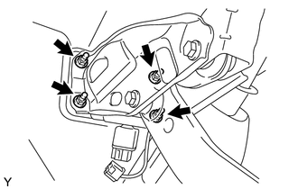
(c) Remove the 4 nuts, and pull out the brake booster assembly. |
|
(d) Remove the gasket from the brake booster assembly.
(e) Loosen the lock nut and then remove the push rod clevis.
7. REMOVE BRAKE VACUUM CHECK VALVE ASSEMBLY
|
(a) Remove the vacuum check valve from the brake booster assembly. Text in Illustration
|
|
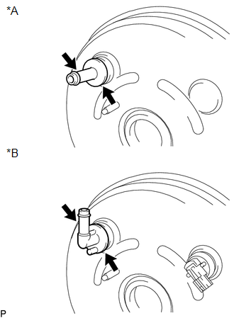
(b) Remove the grommet from the brake booster assembly.
8. REMOVE VACUUM WARNING SWITCH ASSEMBLY (for 2GR-FKS)
Click here
 On-vehicle Inspection
ON-VEHICLE INSPECTION
PROCEDURE
1. CHECK BRAKE BOOSTER ASSEMBLY
(a) Airtightness check.
Text in Illustration
*a
Correct
...
 Inspection
INSPECTION
PROCEDURE
1. INSPECT BRAKE VACUUM CHECK VALVE ASSEMBLY
(a) Check that there is ventilation from the booster to the engine, and
no ventilation from the engine to the booste ...
Other materials:
Satellite Radio Broadcast cannot be Selected or After Selecting Broadcast, Broadcast
cannot be Added into Memory
CAUTION / NOTICE / HINT
NOTICE:
Some satellite radio broadcasts require payment. A contract must be made between
a satellite radio company and the user. If the contract expires, it will not be
possible to listen to the broadcast.
PROCEDURE
1.
CHECK NAVIGATION RECEIVER ...
Torque Converter Clutch Circuit Short to Ground (P074011)
DESCRIPTION
Shift solenoid valve SL is turned on and off by signals from the ECM to control
the hydraulic pressure acting on the lock-up relay valve, which then controls operation
of the lock-up clutch.
DTC No.
DTC Detection Condition
Trouble Area
SA ...
Short in Front Passenger Side Knee Airbag Squib Circuit (B1865/65-B1868/65)
DESCRIPTION
The passenger side knee airbag squib circuit consists of the airbag sensor assembly
and lower No. 2 instrument panel airbag assembly.
The airbag sensor assembly uses this circuit to deploy the airbag when deployment
conditions are met. These DTCs are stored when a malfunction is de ...
