Toyota Tacoma (2015-2018) Service Manual: Components
COMPONENTS
ILLUSTRATION
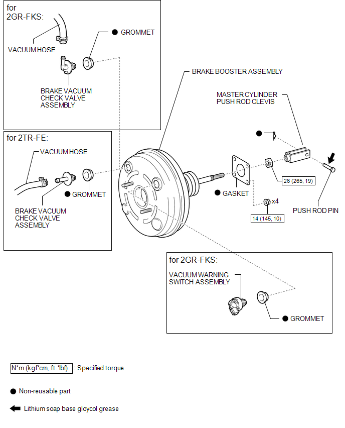
 Brake Booster
...
 On-vehicle Inspection
ON-VEHICLE INSPECTION
PROCEDURE
1. CHECK BRAKE BOOSTER ASSEMBLY
(a) Airtightness check.
Text in Illustration
*a
Correct
...
Other materials:
Fail-safe Chart
FAIL-SAFE CHART
If there is a problem with sensor signals or actuator systems, the skid
control ECU prohibits power supply to the brake actuator assembly and informs
the ECM of a VSC system malfunction.
The brake actuator assembly turns off the solenoids and the ECM stops
its ...
Installation of a mobile two-way radio system
The installation of a mobile two-way radio system in your vehicle could affect
electronic systems such as: ● Multiport fuel injection system/sequential multiport
fuel injection system
● Cruise control system
● Anti-lock brake system
● SRS airbag system
● Seat be ...
Data List / Active Test
DATA LIST / ACTIVE TEST
DATA LIST
NOTICE:
In the table below, the values listed under "Normal Condition" are reference
values. Do not depend solely on these reference values when deciding whether a part
is faulty or not.
HINT:
Using the Techstream to read the Data List allows the ...
