Toyota Tacoma (2015-2018) Service Manual: System Diagram
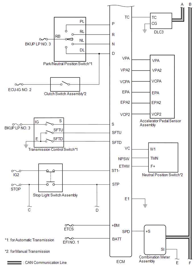
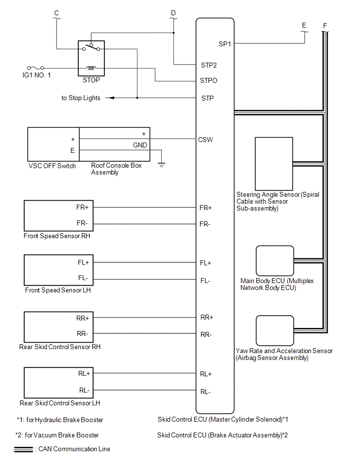
SYSTEM DIAGRAM
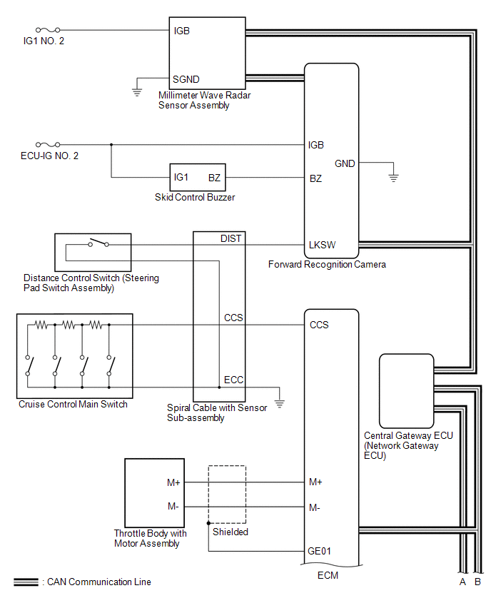
 Communication Table
|
Sender |
Receiver |
Signal |
Line |
|---|---|---|---|
|
ECM |
Millimeter Wave Radar Sensor Assembly |
|
CAN |
|
ECM |
Skid Control ECU (Master Cylinder Solenoid)*1 Skid Control ECU (Brake Actuator Assembly)*2 |
|
CAN |
|
ECM |
Combination Meter Assembly |
|
CAN |
|
ECM |
Forward Recognition Camera |
Cruise control operation signal |
CAN |
|
Millimeter Wave Radar Sensor Assembly |
ECM |
|
CAN |
|
Millimeter Wave Radar Sensor Assembly |
Combination Meter Assembly |
Millimeter wave radar sensor beam axis deviation signal |
CAN |
|
Skid Control ECU (Master Cylinder Solenoid)*1 Skid Control ECU (Brake Actuator Assembly)*2 |
Millimeter Wave Radar Sensor Assembly |
|
CAN |
|
Skid Control ECU (Master Cylinder Solenoid)*1 Skid Control ECU (Brake Actuator Assembly)*2 |
ECM |
|
CAN |
|
Steering Angle Sensor (Spiral Cable with Sensor Sub-assembly) |
Millimeter Wave Radar Sensor Assembly |
|
CAN |
|
Main Body ECU (Multiplex Network Body ECU) |
Millimeter Wave Radar Sensor Assembly |
Destination information signal |
CAN |
|
Yaw Rate and Acceleration Sensor (Airbag Sensor Assembly) |
Millimeter Wave Radar Sensor Assembly |
|
CAN |
- *1: for Hydraulic Brake Booster
- *2: for Vacuum Brake Booster
 Parts Location
PARTS LOCATION
ILLUSTRATION
*A
for Hydraulic Brake Booster
*B
for Vacuum Brake Booster
*C
for Automatic Transmission
...
 How To Proceed With Troubleshooting
CAUTION / NOTICE / HINT
HINT:
Perform the following procedure to troubleshoot the dynamic radar cruise
control system.
*: Use the Techstream.
PROCEDURE
1.
...
Other materials:
Security Horn Assembly
Components
COMPONENTS
ILLUSTRATION
Inspection
INSPECTION
PROCEDURE
1. INSPECT SECURITY HORN ASSEMBLY
(a) Check the operation.
(1) Apply battery voltage and check operation of the security horn assembly.
OK:
Measurement Condition
Spe ...
Disassembly
DISASSEMBLY
PROCEDURE
1. REMOVE CONNECTOR COVER
(a) Disengage the 2 clips to remove the connector cover.
2. REMOVE REAR BUMPER PAD SUB-ASSEMBLY
(a) Separate the 2 license plate light assemblies as shown in the illustration.
...
4WD Control Switch Circuit
WIRING DIAGRAM
PROCEDURE
1.
CONFIRM PROBLEM SYMPTOM
(a) Confirm the problem symptoms.
Result
Result
Proceed to
The 4WD indicator light (green) and 4LO indicator light remain off
A
The 4WD indica ...
