Toyota Tacoma (2015-2018) Service Manual: On-vehicle Inspection
ON-VEHICLE INSPECTION
PROCEDURE
1. INSPECT LOWER NO. 1 INSTRUMENT PANEL AIRBAG ASSEMBLY (for Vehicle not Involved in Collision)
|
(a) Perform a diagnostic system check (See page
|
|
.gif) ).
).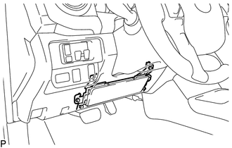
(b) With the lower No. 1 instrument panel airbag assembly installed on the vehicle, perform a visual check. If there are any defects as mentioned below, replace the lower No. 1 instrument panel airbag assembly with a new one:
Cuts, minute cracks or marked discoloration on the lower No. 1 instrument panel airbag assembly.
2. INSPECT LOWER NO. 1 INSTRUMENT PANEL AIRBAG ASSEMBLY (for Vehicle Involved in Collision and Airbag has not Deployed)
|
(a) Perform a diagnostic system check (See page
|
|
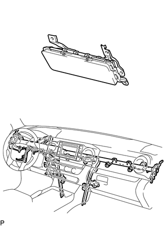
(b) With the lower No. 1 instrument panel airbag assembly removed from the vehicle, perform a visual check. If there are any defects as mentioned below, replace the lower No. 1 instrument panel airbag assembly with a new one:
- Cuts, minute cracks or marked discoloration on the lower No. 1 instrument panel airbag assembly.
- Cracks or other damage to the connector.
- Deformation or cracks on the instrument panel reinforcement.
CAUTION:
For removal and installation procedures of the lower No. 1 instrument panel airbag assembly, be sure to follow the correct procedure.
 Components
COMPONENTS
ILLUSTRATION
...
 Removal
REMOVAL
PROCEDURE
1. PRECAUTION
CAUTION:
Be sure to read Precaution thoroughly before servicing (See page
).
NOTICE:
After turning the ignition switch off, waiting time may be required before ...
Other materials:
Rear Differential Lock Position SW Stuck OFF (P17BB)
DESCRIPTION
This DTC is output when an OFF malfunction of the differential lock indicator
switch is detected.
DTC No.
Detection Item
DTC Detection Condition
Trouble Area
P17BB
Rear Differential Lock Position SW Stuck OFF
...
Components
COMPONENTS
ILLUSTRATION
*1
RADIATOR GRILLE
-
-
ILLUSTRATION
*A
for Type A
*B
for Type B
*C
for Type C
-
-
*1
MILLIMET ...
Installation
INSTALLATION
PROCEDURE
1. INSTALL INSTRUMENT PANEL PASSENGER AIRBAG ASSEMBLY WITHOUT DOOR
(a) Engage the 3 hooks (B).
Text in Illustration
*a
Hooks (A)
*b
Hooks (B)
...
