Toyota Tacoma (2015-2018) Service Manual: Inspection
INSPECTION
PROCEDURE
1. INSPECT CLUTCH DISC ASSEMBLY
NOTICE:
When replacing the clutch disc assembly, make sure to perform an inspection of the flywheel sub-assembly and clutch cover assembly.
|
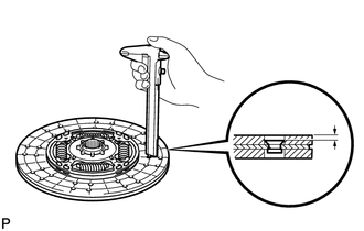
(a) Using a vernier caliper, measure the rivet depth. Minimum rivet depth: 0.3 mm (0.0118 in.) If the depth is less than the minimum, replace the clutch disc assembly. |
|
|
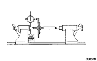
(b) Using a dial indicator, measure the clutch disc assembly runout. Maximum runout: 0.7 mm (0.0276 in.) If the runout is more than the maximum, replace the clutch disc assembly. |
|
2. INSPECT CLUTCH COVER ASSEMBLY
|
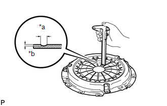
(a) Using a vernier caliper, measure the depth and width of the diaphragm spring wear. Text in Illustration
Maximum Wear:
If the depth or width is more than the maximum, replace the clutch cover assembly. |
|
|
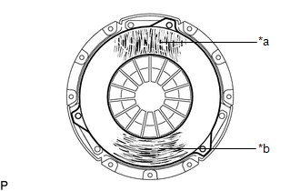
(b) Perform a visual inspection of the clutch cover assembly. Text in Illustration
(1) Inspect for hair cracks or scratches extending from the center outwards, or discoloration. (2) Inspect for hair cracks in a circular pattern, discoloration or excessive wear. If there is any damage, replace the clutch cover assembly. |
|
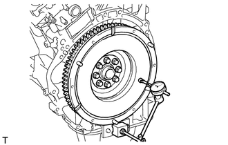
3. INSPECT FLYWHEEL SUB-ASSEMBLY
|
(a) Using a dial indicator, check the flywheel sub-assembly runout. Maximum runout: 0.1 mm (0.00393 in.) If the runout is more than the maximum, replace the flywheel sub-assembly. |
|
|
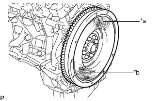
(b) Perform a visual inspection of the flywheel sub-assembly. Text in Illustration
(1) Inspect for hair cracks or scratches extending from the center outwards, or discoloration. (2) Inspect for hair cracks in a circular pattern, discoloration or excessive wear. If there is any damage, replace the flywheel sub-assembly. |
|
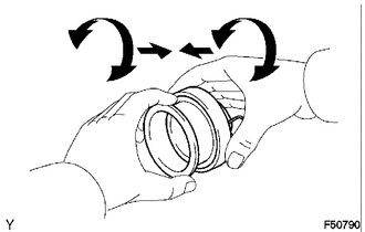
4. INSPECT CLUTCH RELEASE BEARING ASSEMBLY
|
(a) Check that the clutch release bearing assembly moves smoothly without abnormal resistance by turning the sliding parts of the clutch release bearing assembly (contact surfaces with the clutch cover assembly) while applying force in the axial direction. |
|
(b) Inspect the clutch release bearing assembly for damage or wear.
If necessary, replace the clutch release bearing assembly.
 Components
COMPONENTS
ILLUSTRATION
...
 Removal
REMOVAL
PROCEDURE
1. REMOVE MANUAL TRANSMISSION ASSEMBLY
(See page )
2. REMOVE CLUTCH RELEASE FORK SUB-ASSEMBLY
(a) Remove the clutch release fork sub-assembly with the clutch releas ...
Other materials:
Installation
INSTALLATION
PROCEDURE
1. INSTALL REAR SEAT 3 POINT TYPE OUTER BELT ASSEMBLY
(a) Before installing the rear seat 3 point type outer belt assembly,
check the ELR function.
Text in Illustration
*a
Unlock
*b
...
Operation Check
OPERATION CHECK
1. CHECK AUTO OPERATION
NOTICE:
Make sure that initialization has been completed before inspection (See
page ).
The sliding roof auto operation can be customized. Make sure that the
auto operation is ON (See page ).
HINT:
When pressing the switch for ...
Problem Symptoms Table
PROBLEM SYMPTOMS TABLE
HINT:
Use the table below to help determine the cause of the problem symptom.
The potential causes of the symptoms are listed in order of probability
in the "Suspected Area" column of the table. Check each symptom by checking
the suspected areas ...
