Toyota Tacoma (2015-2018) Service Manual: Adjustment
ADJUSTMENT
CAUTION / NOTICE / HINT
HINT:
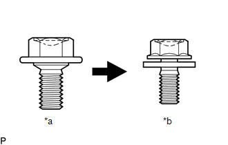
- Centering bolts are used to mount the hood hinge and hood lock assembly. The hood and hood lock assembly cannot be adjusted with the centering bolts installed. Substitute the centering bolts with standard bolts when making adjustments.
- Specified torque for standard bolts is shown in the standard bolt chart
(See page
.gif) ). Text in Illustration
). Text in Illustration
*a
Centering Bolt
*b
Standard Bolt
PROCEDURE
1. INSPECT HOOD SUB-ASSEMBLY
(a) Check that the clearance measurements of areas "A" though "D" are within each standard range.
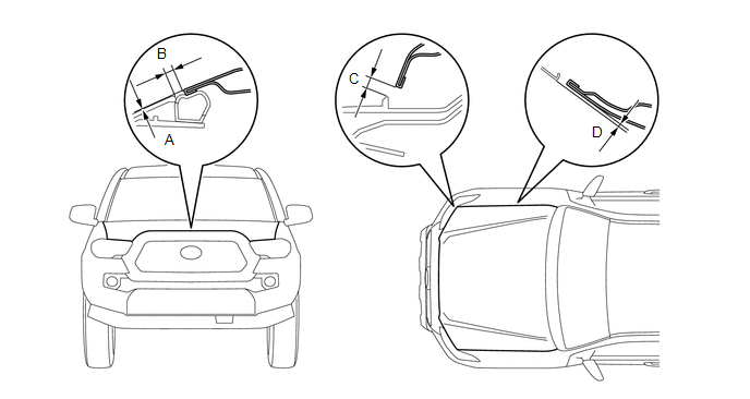
Standard Clearance:
|
Area |
Measurement |
Area |
Measurement |
|---|---|---|---|
|
A |
-1.4 to 1.6 mm (-0.055 to 0.063 in.) |
B |
4.9 to 7.9 mm (0.193 to 0.311 in.) |
|
C |
4.9 to 7.9 mm (0.193 to 0.311 in.) |
D |
-1.4 to 1.6 mm (-0.055 to 0.063 in.) |
2. ADJUST HOOD SUB-ASSEMBLY
|
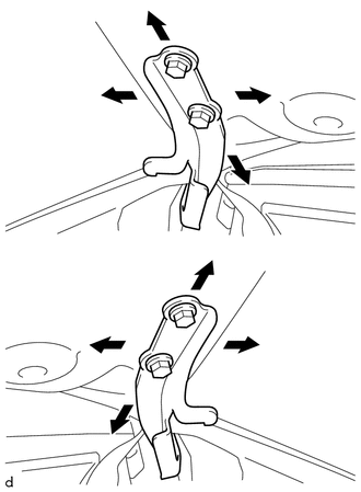
(a) Horizontally and vertically adjust the hood. (1) Loosen the 4 hinge bolts of the hood. (2) Adjust the clearance between the hood and front fender by moving the hood. (3) Tighten the 4 hinge bolts after adjustment. Torque: 13 N┬Ěm {133 kgf┬Ěcm, 10 ft┬Ělbf} |
|
|
(b) Adjust the height of the front end of the hood using the hood bumper cushions. (1) Adjust the 2 hood bumper cushions so that the heights of the hood and fenders are aligned. |
|
(c) Adjust the hood lock assembly.
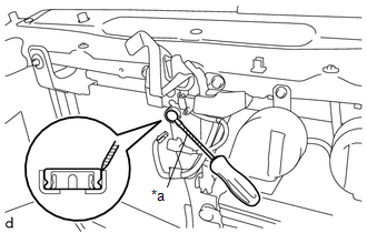
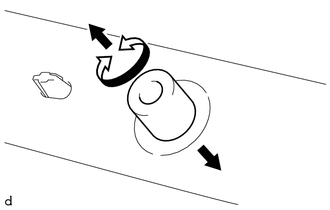
(1) Using a screwdriver with its tip wrapped in protective tape, remove the hood lock nut cap.
Text in Illustration|
*a |
Protective Tape |
|
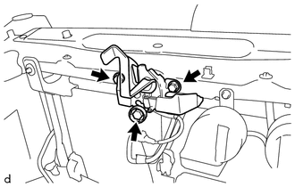
(2) Loosen the 3 bolts. |
|
|
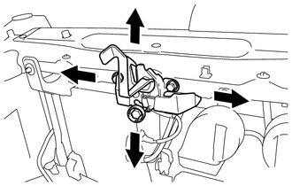
(3) Adjust the hood lock assembly and tighten the 3 bolts. Torque: 8.0 N┬Ěm {82 kgf┬Ěcm, 71 in┬Ělbf} |
|
|
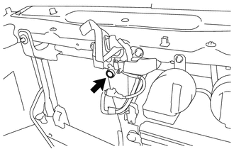
(d) Install a new hood lock nut cap. |
|
 Hood
Hood
...
 Components
COMPONENTS
ILLUSTRATION
ILLUSTRATION
ILLUSTRATION
...
Other materials:
Air Conditioning Compressor Magnetic Clutch Circuit
DESCRIPTION
When the air conditioning amplifier assembly is turned on, a magnetic clutch
on signal is sent from the MGC terminal of the air conditioning amplifier assembly.
Then, the MG CLT relay turns on to operate the magnetic clutch assembly.
WIRING DIAGRAM
CAUTION / NOTICE / HINT
NO ...
Clutch Switch Circuit
DESCRIPTION
Clutch switch circuit inspection is necessary for manual transmission vehicles.
When the clutch pedal is released, the ECM receives the positive (+) battery
voltage through the ECU-IG NO. 2 fuse and ignition switch. While the clutch pedal
is depressed, the clutch switch assembly se ...
Playing an audio CD and MP3/WMA/AAC discs
Insert disc or select ÔÇťCDÔÇŁ on the ÔÇťSelect Audio SourceÔÇŁ screen to begin listening
to a CD.
Audio control screen
1. ÔÇťSelect Audio SourceÔÇŁ screen appears
2. Audio CD
Displaying the track list
MP3/WMA/AAC
Displaying the folder list
3. Random playback
4. Repeat play
5. Pause
...
