Toyota Tacoma (2015-2018) Service Manual: Components
COMPONENTS
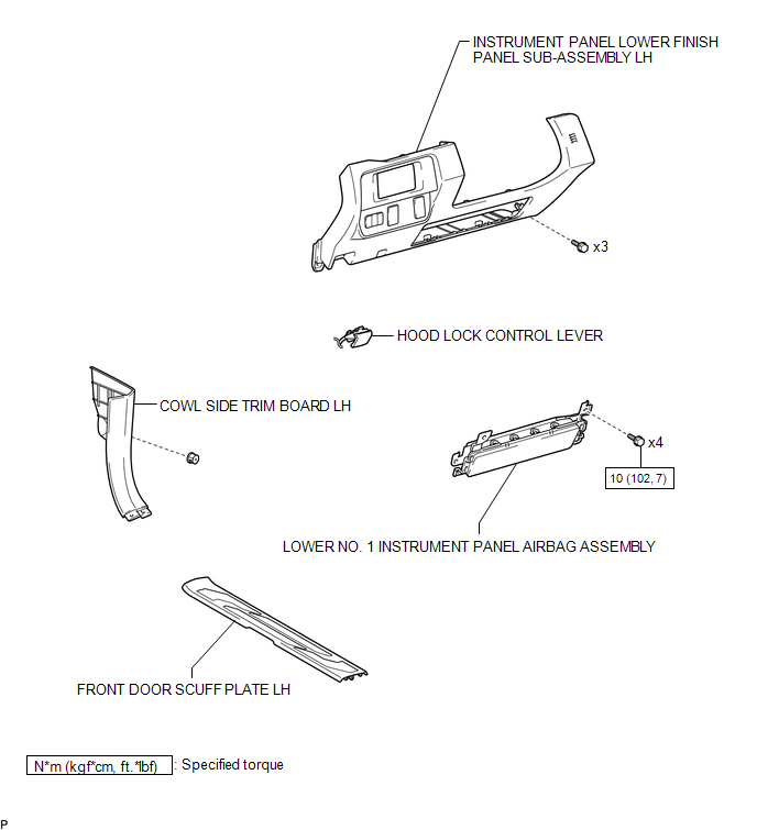
ILLUSTRATION

 On-vehicle Inspection
ON-VEHICLE INSPECTION
PROCEDURE
1. INSPECT LOWER NO. 1 INSTRUMENT PANEL AIRBAG ASSEMBLY (for Vehicle not Involved
in Collision)
(a) Perform a diagnostic system check (See page
).
...
Other materials:
Lost Communication with ECM (C1437)
DESCRIPTION
The skid control ECU (brake actuator assembly) receives signals from the ECM
via the CAN communication system.
DTC No.
Detection Item
DTC Detection Condition
Trouble Area
C1437
Lost Communication with ECM
...
Inverter Relay
On-vehicle Inspection
ON-VEHICLE INSPECTION
PROCEDURE
1. INSPECT INVERTER RELAY
(a) Check the resistance.
(1) Measure the resistance according to the value(s) in the table below.
Standard Resistance:
Tester Connection
Condition
...
Remote Up / Down Function does not Operate
DESCRIPTION
When the ignition switch is ON, the power window regulator master switch assembly
sends remote up/down signals to each power window regulator motor assembly via the
LIN communication line.
WIRING DIAGRAM
CAUTION / NOTICE / HINT
NOTICE:
The power window control system u ...
