Toyota Tacoma (2015-2018) Service Manual: Removal
REMOVAL
PROCEDURE
1. PRECAUTION
CAUTION:
Be sure to read Precaution thoroughly before servicing (See page
.gif) ).
).
NOTICE:
After turning the ignition switch off, waiting time may be required before disconnecting the cable from the negative (-) battery terminal. Therefore, make sure to read the disconnecting the cable from the negative (-) battery terminal notices before proceeding with work.
Click here
2. DISCONNECT CABLE FROM NEGATIVE BATTERY TERMINAL
CAUTION:
Wait at least 90 seconds after disconnecting the cable from the negative (-) battery terminal to prevent airbag and seat belt pretensioner activation.
NOTICE:
When disconnecting the cable, some systems need to be initialized after the cable is reconnected.
Click here
3. REMOVE FRONT DOOR SCUFF PLATE LH
4. REMOVE COWL SIDE TRIM BOARD LH
5. REMOVE INSTRUMENT PANEL LOWER FINISH PANEL SUB-ASSEMBLY LH
6. DISCONNECT HOOD LOCK CONTROL LEVER SUB-ASSEMBLY
7. REMOVE LOWER NO. 1 INSTRUMENT PANEL AIRBAG ASSEMBLY
|
(a) Remove the 4 bolts. |
|
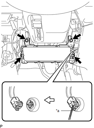
(b) Using a screwdriver with its tip wrapped in protective tape, release the airbag connector lock.
(c) Disconnect the airbag connector to remove the lower No. 1 instrument panel airbag assembly.
Text in Illustration|
*a |
Protective Tape |
NOTICE:
When handling the airbag connector, take care not to damage the airbag wire harness.
 On-vehicle Inspection
ON-VEHICLE INSPECTION
PROCEDURE
1. INSPECT LOWER NO. 1 INSTRUMENT PANEL AIRBAG ASSEMBLY (for Vehicle not Involved
in Collision)
(a) Perform a diagnostic system check (See page
).
...
 Disposal
DISPOSAL
CAUTION / NOTICE / HINT
CAUTION:
Before performing pre-disposal deployment of any SRS part, review and closely
follow all applicable environmental and hazardous material regulations. Pre ...
Other materials:
Dtc Check / Clear
DTC CHECK / CLEAR
NOTICE:
The steering lock ECU (steering lock actuator or UPR bracket assembly)
does not store history DTCs. If any DTCs are output, confirm and record
them as soon as possible. Do not turn the engine switch off or clear the
DTCs until the DTCs are confirmed an ...
Engine Immobiliser System Circuit Short to Battery (B279A12)
DESCRIPTION
When the communication line (IMI - EFIO) between the ECM and certification ECU
(smart key ECU assembly) is stuck high, the ECM stores this DTC.
DTC Code
DTC Detection Condition
Trouble Area
DTC Output Confirmation Operation
...
Brake System (P157800)
DESCRIPTION
This DTC is stored when a malfunction is detected in the vehicle stability control
system.
DTC No.
Detection Item
DTC Detection Condition
Trouble Area
MIL
P157800
Brake System
While the igni ...
