Toyota Tacoma (2015-2018) Service Manual: Neutral Position Switch
Components
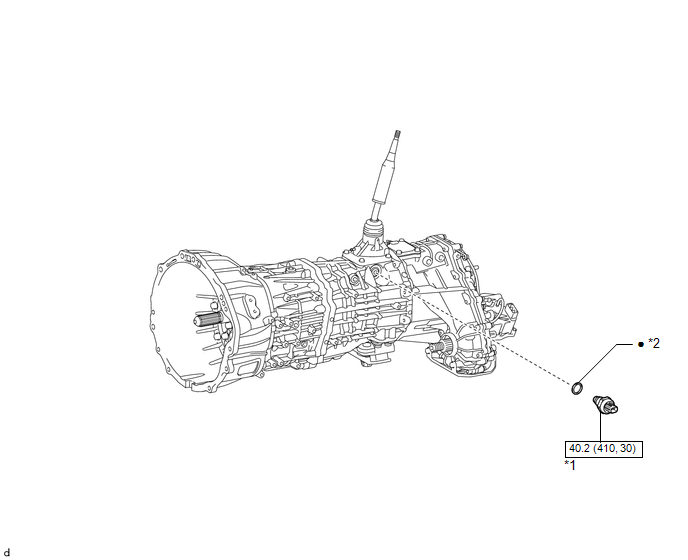
COMPONENTS
ILLUSTRATION
|
*1 |
NEUTRAL POSITION SWITCH |
*2 |
GASKET |
.png) |
N*m (kgf*cm, ft.*lbf): Specified torque |
â—Ź |
Non-reusable part |
Installation
INSTALLATION
PROCEDURE
1. INSTALL NEUTRAL POSITION SWITCH
|
(a) Using SST, install the neutral position switch and a new gasket to the transmission case. SST: 09817-16011 Torque: 40.2 N·m {410 kgf·cm, 30 ft·lbf} |
|
(b) Connect the connector.
Removal
REMOVAL
PROCEDURE
1. REMOVE NEUTRAL POSITION SWITCH
|
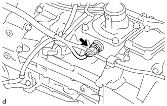
(a) Disconnect the connector. |
|
|
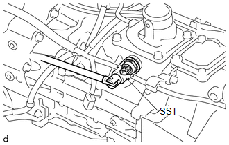
(b) Using SST, remove the neutral position switch and gasket from the transmission case. SST: 09817-16011 |
|
.png)
 Manual Transmission Unit
Components
COMPONENTS
ILLUSTRATION
ILLUSTRATION
*1
SHIFT DETENT BALL PLUG
*2
SHIFT DETENT BALL COMPRESSION SPRING
*3
M ...
 Output Shaft
Components
COMPONENTS
ILLUSTRATION
Disassembly
DISASSEMBLY
PROCEDURE
1. REMOVE FRONT OUTPUT SHAFT BEARING
(a) Temporarily install the manual transmission output shaft rear set ...
Other materials:
Heater Relay
Inspection
INSPECTION
PROCEDURE
1. INSPECT HEATER RELAY
(a) Check the resistance.
(1) Using an ohmmeter, measure the resistance between each terminal.
Standard:
Tester Connection
Specified Condition
3 - 4
...
Confirm Vehicle Headunit Functionality
PROCEDURE
1.
CHECK CUSTOMER'S CELLULAR PHONE COMPATIBILITY
(a) Go to TIS "Bluetooth" Compatibility Portal and check if the cellular phone
is compatible.
Result
Result
Proceed to
Cellular phone is compatible
...
Skid Control Buzzer Circuit (C1A4A)
DESCRIPTION
Based on dynamic radar cruise control system operation, the forward recognition
camera provides warnings to the driver by sounding the skid control buzzer.
DTC C1A4A is stored when a malfunction is detected in the skid control buzzer
circuit.
DTC No.
Detectio ...
