Toyota Tacoma (2015-2018) Service Manual: Output Shaft
Components
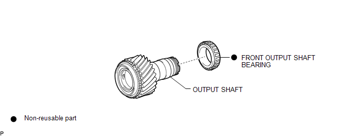
COMPONENTS
ILLUSTRATION
Disassembly
DISASSEMBLY
PROCEDURE
1. REMOVE FRONT OUTPUT SHAFT BEARING
|
(a) Temporarily install the manual transmission output shaft rear set nut to the output shaft. Text in Illustration
|
|
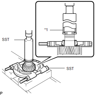
(b) Using SST and a press, remove the front output shaft bearing from the output shaft.
SST: 09316-60011
09316-00011
SST: 09950-00020
Inspection
INSPECTION
PROCEDURE
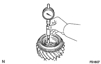
1. INSPECT OUTPUT SHAFT
|
(a) Using a cylinder gauge, measure the inside diameter of the output shaft. Standard inside diameter: 45.009 to 45.025 mm (1.77201 to 1.7726 in.) Maximum inside diameter: 45.025 mm (1.7726 in.) If the diameter is more than the maximum, replace the output shaft. |
|
Reassembly
REASSEMBLY
PROCEDURE
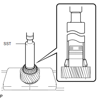
1. INSTALL FRONT OUTPUT SHAFT BEARING
|
(a) Using SST and a press, install a new front output shaft bearing to the output shaft. SST: 09316-60011 09316-00011 |
|
 Neutral Position Switch
Components
COMPONENTS
ILLUSTRATION
*1
NEUTRAL POSITION SWITCH
*2
GASKET
N*m (kgf*cm, ft.*lbf): Specified torque
...
 Suspension
...
Other materials:
Removal
REMOVAL
CAUTION / NOTICE / HINT
HINT:
Use the same procedure for the RH and LH sides.
The procedure described below is for the LH side.
PROCEDURE
1. REMOVE FRONT DOOR GLASS RUN
2. REMOVE FRONT DOOR GLASS OUTER WEATHERSTRIP ASSEMBLY
(See page
)
3. REMOVE NO. 1 BLAC ...
Fender Panel Mudguard
Components
COMPONENTS
ILLUSTRATION
ILLUSTRATION
Installation
INSTALLATION
CAUTION / NOTICE / HINT
HINT:
Use the same procedure for the RH side and LH side.
The following procedure is for the LH side.
PROCEDURE
1. INSTALL FRONT FENDER MUDGUARD
(a) Install the fron ...
Interior Illumination Light
Components
COMPONENTS
ILLUSTRATION
Removal
REMOVAL
PROCEDURE
1. REMOVE INSTRUMENT PANEL LOWER CENTER FINISH PANEL
(See page )
2. REMOVE NO. 1 INTERIOR ILLUMINATION LIGHT ASSEMBLY
(a) Turn the No. 1 interior illumination light assembly in the direction
indicated by the ...
