Toyota Tacoma (2015-2018) Service Manual: Manual Transmission Unit
Components
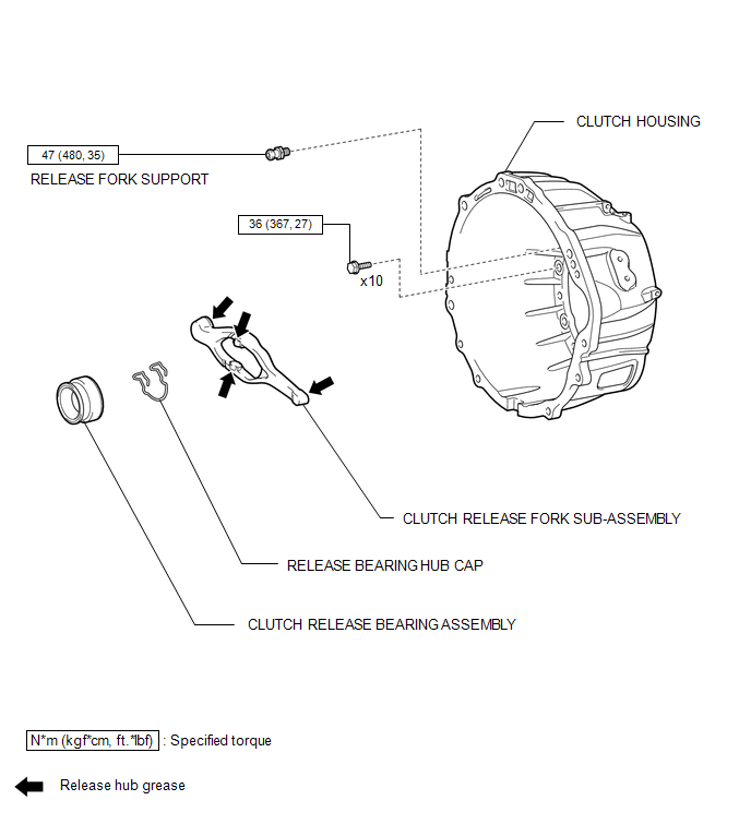
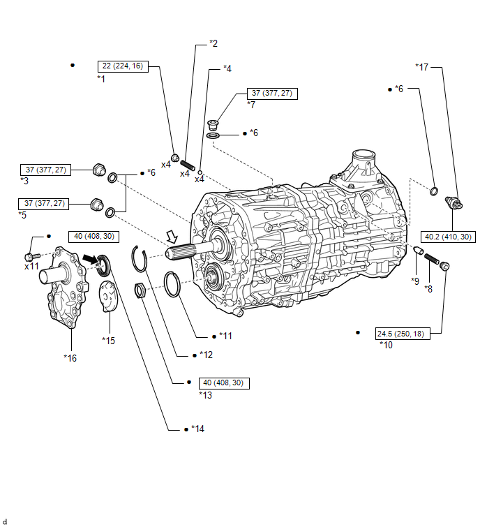
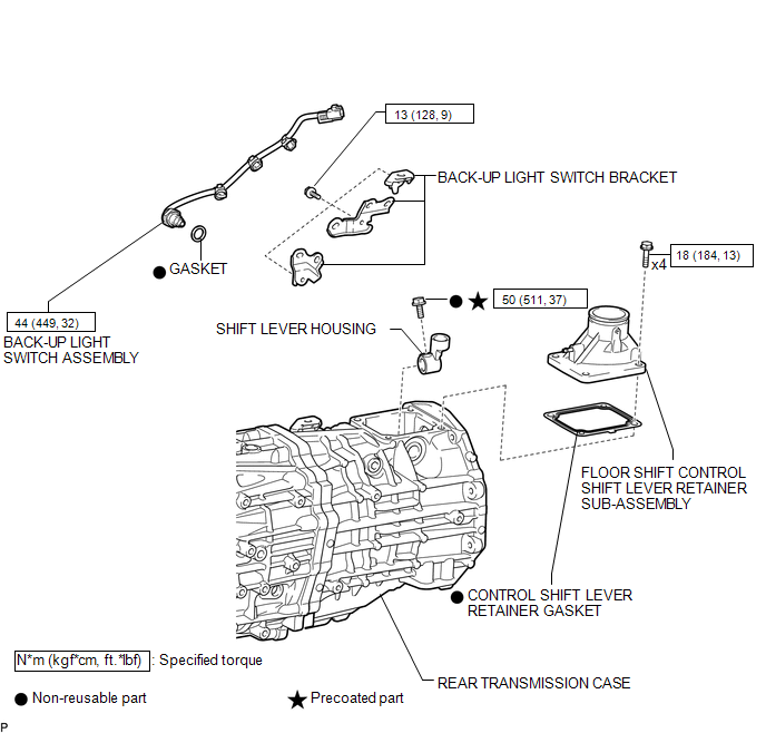
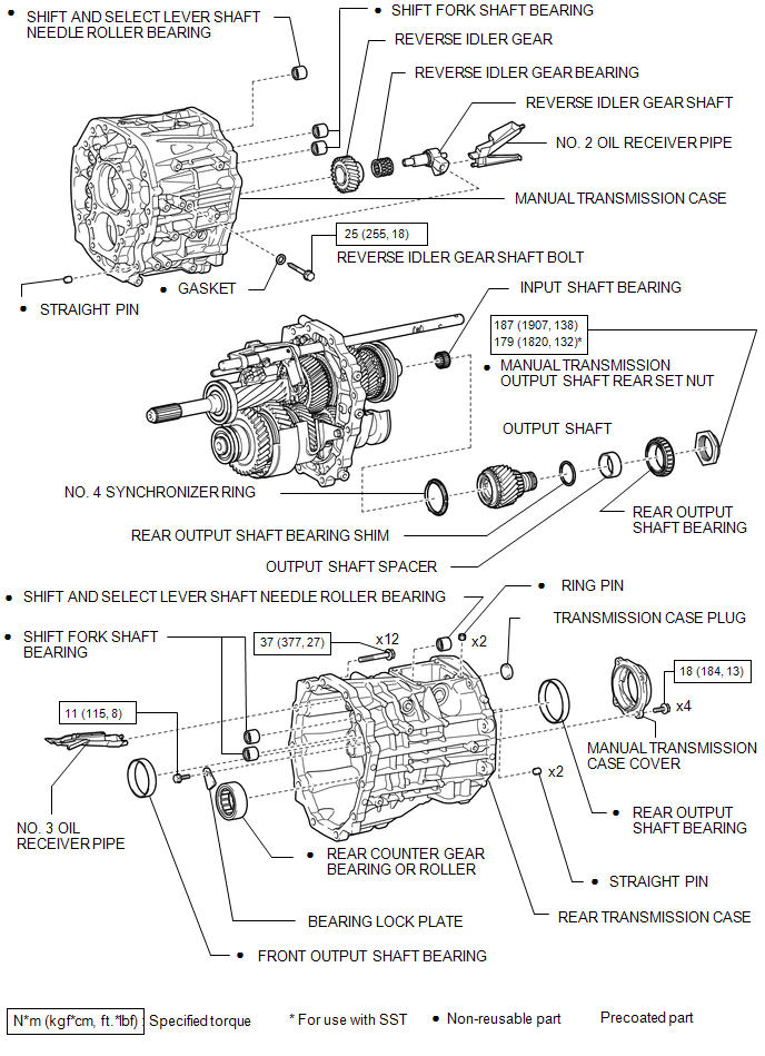
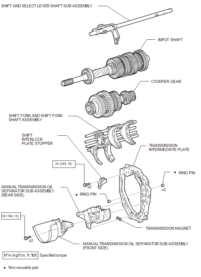
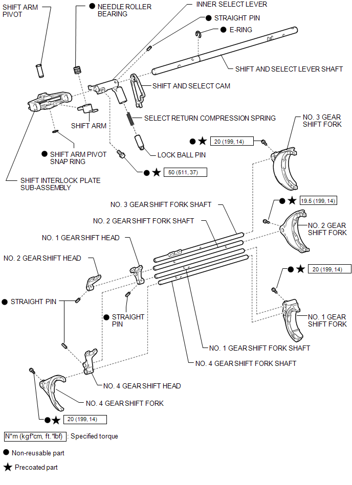
COMPONENTS
ILLUSTRATION
ILLUSTRATION
|
*1 |
SHIFT DETENT BALL PLUG |
*2 |
SHIFT DETENT BALL COMPRESSION SPRING |
|
*3 |
MANUAL TRANSMISSION FILLER PLUG |
*4 |
SHAFT DETENT BALL |
|
*5 |
DRAIN PLUG SUB-ASSEMBLY |
*6 |
GASKET |
|
*7 |
STRAIGHT SCREW PLUG WITH HEAD |
*8 |
SHIFT AND SELECT LEVER SPRING |
|
*9 |
LOCK BALL PIN |
*10 |
NO. 2 STRAIGHT SCREW PLUG WITH HEAD |
|
*11 |
FRONT BEARING SHAFT SNAP RING |
*12 |
INPUT SHAFT SHAFT SNAP RING |
|
*13 |
COUNTER GEAR SHAFT NUT |
*14 |
FRONT TRANSMISSION BEARING RETAINER OIL SEAL |
|
*15 |
NO. 1 OIL RECEIVER PIPE |
*16 |
FRONT BEARING RETAINER |
|
*17 |
NEUTRAL POSITION SWITCH |
- |
- |
.png) |
N*m (kgf*cm, ft.*lbf) : Specified torque |
ã |
Non-reusable part |
.png) |
MP Grease |
.png) |
Clutch spline grease |
|
ã |
Precoated part |
- |
- |
ILLUSTRATION
ILLUSTRATION
ILLUSTRATION
ILLUSTRATION
Inspection
INSPECTION
PROCEDURE
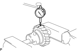
1. INSPECT REVERSE IDLER GEAR RADIAL CLEARANCE
|
(a) Using a dial indicator, measure the radial clearance. Standard clearance: 0.015 to 0.050 mm (0.000591 to 0.00196 in.) Maximum clearance: 0.050 mm (0.00196 in.) If the clearance is more than the maximum, replace the needle roller bearing. |
|
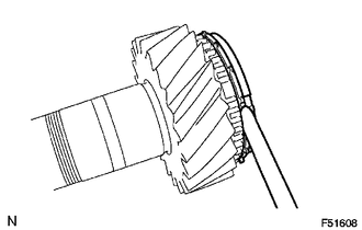
2. INSPECT NO. 4 SYNCHRONIZER RING
|
(a) Using a feeler gauge, measure the clearance between the No. 4 synchronizer ring and gear spline. Standard clearance: 0.82 to 1.48 mm (0.0323 to 0.0582 in.) Maximum clearance: 0.82 mm (0.0323 in.) If the clearance is less than the minimum, replace the No. 4 synchronizer ring. |
|
(b) Coat the output shaft cone with gear oil.
|
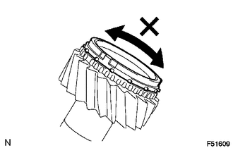
(c) Check the braking effect of the synchronizer ring. (1) Turn the synchronizer ring in both directions while pushing it against the output shaft cone. Check that the ring locks in both directions. If No. 4 synchronizer ring turns, replace it. |
|
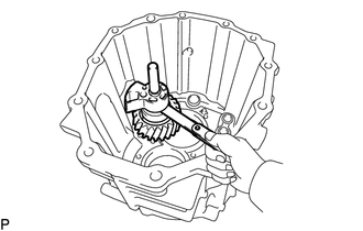
3. INSPECT REVERSE IDLER GEAR
(a) Install the reverse idler gear with the reverse idler gear shaft bolt.
Torque:
25 Nôñm {255 kgfôñcm, 18 ftôñlbf}
|
(b) Using a feeler gauge, measure the thrust clearance. Standard clearance: 0.196 to 0.939 mm (0.0078 to 0.0369 in.) Maximum clearance: 0.939 mm (0.0369 in.) If the clearance is more than the maximum, replace the reverse idler gear shaft, reverse idler gear or transmission case. |
|
(c) Remove the reverse idler gear.
 Vehicle Speed Sensor "A" No Signal (P050031)
DESCRIPTION
Vehicles, which are equipped with ABS (Anti-lock Brake System), detect the vehicle
speed using the skid control ECU (brake actuator assembly) and speed sensors. Each
speed sensor moni ...
 Neutral Position Switch
Components
COMPONENTS
ILLUSTRATION
*1
NEUTRAL POSITION SWITCH
*2
GASKET
N*m (kgf*cm, ft.*lbf): Specified torque
...
Other materials:
Operation Check
OPERATION CHECK
CHECK LANE DEPARTURE ALERT MAIN SWITCH
(a) Check the lane departure alert main switch (steering pad switch assembly)
on/off operation.
(1) Turn the ignition switch to ON.
(2) Confirm that the lane departure alert indicator (green) in the combination
meter assembly illuminates ...
Vehicle Speed Signal Circuit between Radio Receiver and Combination Meter
DESCRIPTION
for Audio Function:
The radio and display receiver assembly receives a vehicle speed signal
from the combination meter assembly and sends the signal to radio and display
receiver assembly.
for Automatic Sound Levelizer (ASL):
This circuit is necessary fo ...
Installation
INSTALLATION
PROCEDURE
1. INSTALL ENGINE WATER PUMP ASSEMBLY
(a) Install the engine water pump assembly and a new gasket to the timing
chain cover assembly with the 15 bolts.
Torque:
for Bolt A and B :
11 Nôñm {112 kgfôñcm, 8 ftôñlbf}
for Bolt C :
21 Nôñm {214 kgf ...
