Toyota Tacoma (2015-2018) Service Manual: Motor Power Supply Voltage Circuit (C142B-C146D)
DESCRIPTION
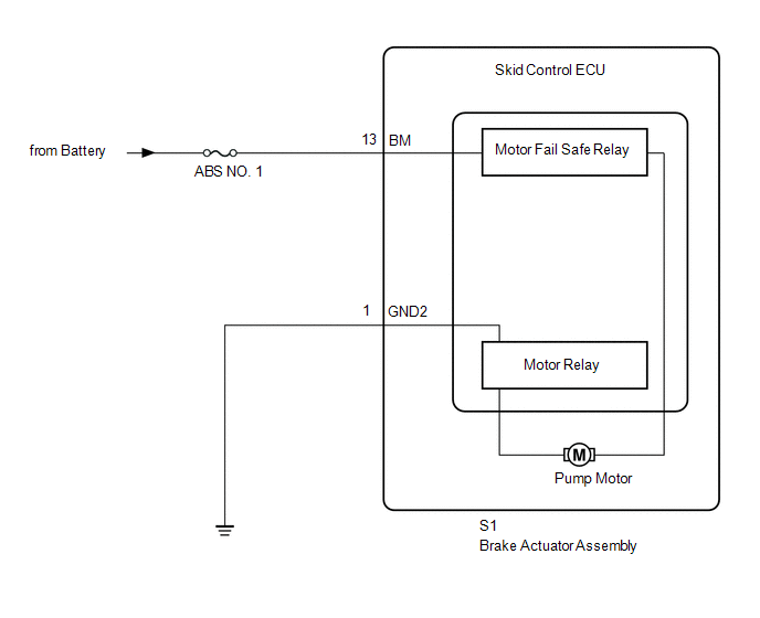
The motor relay and motor fail-safe relay are built into the brake actuator assembly.
During ABS, TRAC, VSC, or brake assist operation, the skid control ECU (brake actuator assembly) turns on the motor relay to run the pump motor in the brake actuator assembly.
When a motor system DTC is stored, the motor fail-safe relay cuts the power source supply to the motor relay for fail-safe operation.
These DTCs may be stored when the voltage to the motor relay power source (BM terminal) is lower than the DTC detection condition due to low output from the battery or alternator.
|
DTC No. |
Detection Item |
DTC Detection Condition |
Trouble Area |
|---|---|---|---|
|
C142B |
Motor Power Supply Voltage Circuit |
When voltage at +BS terminal is 9.5 V or higher, open in BM terminal continues for 1 second or more. |
|
|
C146C |
Open in ABS Motor Relay Circuit |
When voltage at +BS terminal is 9.5 V or higher and motor relay ON while control operates, relay contact OFF condition continues for 0.12 seconds or more. |
|
|
C146D |
Short in ABS Motor Relay Circuit |
Either of the following is detected:
|
|
HINT:
DTC will be output when conditions for either of the patterns in the table above are met.
WIRING DIAGRAM
CAUTION / NOTICE / HINT
NOTICE:
- When replacing the skid control ECU (brake actuator assembly), perform
zero point calibration and store system information (See page
.gif) ).
).
- Inspect the fuses for circuits related to this system before performing the following inspection procedure.
HINT:
When C1241 and/or C1417 is output together with C142B, C146C and/or C146D inspect and repair the trouble areas indicated by C1241 and/or C1417 first.
- for C1241: (See page )
- for C1417: (See page )
PROCEDURE
|
1. |
CHECK TERMINAL VOLTAGE (BM TERMINAL) |
(a) Turn the ignition switch off.
(b) Make sure that there is no looseness at the locking part and the connecting part of the connectors.
|
(c) Disconnect the S1 skid control ECU (brake actuator assembly) connector. |
|
(d) Measure the voltage according to the value(s) in the table below.
Standard Voltage:
|
Tester Connection |
Switch Condition |
Specified Condition |
|---|---|---|
|
S1-13 (BM) - Body ground |
Always |
11 to 14 V |
|
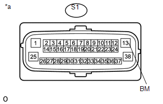
*a |
Front view of wire harness connector (to Skid Control ECU [Brake Actuator Assembly]) |
| NG | .gif) |
REPAIR OR REPLACE HARNESS OR CONNECTOR (BM CIRCUIT) |
|
.gif)
|
2. |
CHECK HARNESS AND CONNECTOR (GND2 TERMINAL) |
|
(a) Measure the resistance according to the value(s) in the table below. Standard Resistance:
|
|
.png)
| NG | |
REPAIR OR REPLACE HARNESS OR CONNECTOR (GND2 CIRCUIT) |
|
|
3. |
RECONFIRM DTC |
HINT:
These codes are stored when a problem is identified in the skid control ECU (brake actuator assembly). The motor relay is in the skid control ECU (brake actuator assembly). Therefore, motor relay inspections and motor relay unit inspections cannot be performed. Be sure to check if any DTCs are output before replacing the brake actuator assembly.
(a) Reconnect the S1 skid control ECU (brake actuator assembly) connector.
(b) Clear the DTC (See page
).
(c) Turn the ignition switch off.
(d) Start the engine.
(e) Drive the vehicle at a speed of 20 km/h (12 mph) or more for 30 seconds or more.
(f) Check if the same DTC is recorded (See page
).
|
Result |
Proceed to |
|---|---|
|
DTCs C142B, C146C and C146D are not output |
A |
|
DTCs C142B, C146C and/or C146D are output |
B |
HINT:
- If a speed signal of 6 km/h (4 mph) or more is input to the skid control ECU (brake actuator assembly), with the ignition switch to ON and the stop light switch off, the ECU performs self diagnosis of the motor and solenoid circuits.
- If the normal system code is output (the trouble code is not output), slightly jiggle the connectors, wire harness, and fuses of the skid control ECU (brake actuator assembly). Make sure that no DTCs are output.
- If any DTCs are output while jiggling a connector or wire harness from the skid control ECU (brake actuator assembly), inspect and repair the connector or wire harness.
- The DTCs were probably output due to a bad connection of the connector terminal.
| A | |
USE SIMULATION METHOD TO CHECK |
| B | |
REPLACE BRAKE ACTUATOR ASSEMBLY |
 Motor Malfunction (C1427)
DESCRIPTION
DTC No.
Detection Item
DTC Detection Condition
Trouble Area
C1427
Motor Malfunction
Actuator pump motor ...
 Motor Circuit Malfunction (C1428)
DESCRIPTION
DTC No.
Detection Item
DTC Detection Condition
Trouble Area
C1428
Motor Circuit Malfunction
With the mot ...
Other materials:
Disassembly
DISASSEMBLY
PROCEDURE
1. REMOVE OIL PUMP RELIEF VALVE
(a) Using a 27 mm socket wrench, remove the oil pump relief valve plug.
(b) Remove the oil pump relief valve spring and oil pump relief valve.
(c) Remove the spring and relief valve.
2. R ...
Problem Symptoms Table
PROBLEM SYMPTOMS TABLE
HINT:
Use the table below to help determine the cause of problem symptoms.
If multiple suspected areas are listed, the potential causes of the symptoms
are listed in order of probability in the "Suspected Area" column of the
table. Check each sy ...
Precaution
PRECAUTION
1. PRECAUTIONS WHEN USING TECHSTREAM
(a) When using the Techstream to troubleshoot the engine immobiliser system:
Connect the Techstream to the DLC3 while the ignition switch is off, and turn
a door courtesy light switch on and off at 1.5-second intervals until communication
betwee ...
