Toyota Tacoma (2015-2018) Service Manual: Removal
REMOVAL
CAUTION / NOTICE / HINT
NOTICE:
- Before starting the work, make sure that the ignition switch is off and depress the brake pedal more than 20 times.
- As high pressure is applied to the No. 1 brake actuator tube, never deform it.
- Do not turn the ignition switch to ON until the work is completed.
HINT:
When pressure in the accumulator is released, reaction force becomes lighter and stroke becomes longer.
PROCEDURE
1. DRAIN BRAKE FLUID
NOTICE:
Immediately wash off any brake fluid off immediately that comes into contact with a painted surface.
2. REMOVE LOWER NO. 1 INSTRUMENT PANEL AIRBAG ASSEMBLY
(See page .gif) )
)
3. SEPARATE DRIVER SIDE JUNCTION BLOCK
4. SEPARATE MASTER CYLINDER PUSH ROD CLEVIS
5. REMOVE HYDRAULIC BRAKE BOOSTER
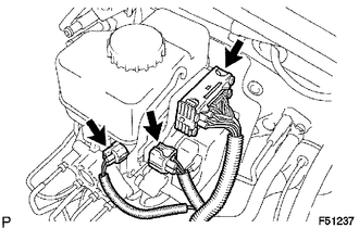
(a) Disconnect the 3 connectors from the hydraulic brake booster.
|
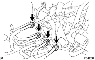
(b) Using a union nut wrench, disconnect the 4 brake lines from the hydraulic brake booster. |
|
|
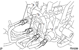
(c) Use tags or labels to identify the place to reconnect each line. Text in Illustration
|
|
|
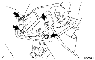
(d) Remove the 4 nuts and pull out the hydraulic brake booster. |
|
(e) Remove the brake booster gasket.
 Disassembly
DISASSEMBLY
PROCEDURE
1. REMOVE BRAKE ACTUATOR BRACKET NO. 1
(a) Using a hexagon wrench (5 mm), remove the screw and brake actuator bracket
No. 1.
(b) Using a screwdriver, remove th ...
 Inspection
INSPECTION
PROCEDURE
1. INSPECT BRAKE BOOSTER PUMP ASSEMBLY
(a) Connect the positive (+) lead from the battery to the red cable of the pump,
and the negative (-) lead to the black cable.
(b) C ...
Other materials:
Components
COMPONENTS
ILLUSTRATION
*A
for Driver Side
-
-
*1
FRONT SEAT CUSHION HEATER ASSEMBLY
*2
SEPARATE TYPE FRONT SEAT CUSHION COVER
*3
TAG PIN
-
-
...
Communication Malfunction between ECUs Connected by LIN (B2785)
DESCRIPTION
The certification ECU (smart key ECU assembly) monitors communication between
all the ECUs connected to the certification bus lines. When the certification ECU
(smart key ECU assembly) detects errors in communication with all the ECUs connected
to the certification bus lines at a ...
Diagnostic Trouble Code Chart
DIAGNOSTIC TROUBLE CODE CHART
HINT:
If a trouble code is output during the DTC check, inspect the trouble areas listed
for that code. For details of the code, refer to the "See page" below.
Certification ECU (Smart Key ECU Assembly)
DTC Code
Detection Item
...
