Toyota Tacoma (2015-2018) Service Manual: Vehicle Speed Sensor "A" No Signal (P050031)
DESCRIPTION
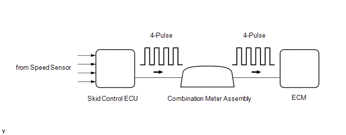
Vehicles, which are equipped with ABS (Anti-lock Brake System), detect the vehicle speed using the skid control ECU (brake actuator assembly) and speed sensors. Each speed sensor monitors the wheel rotation speed and sends a signal to the skid control ECU. The skid control ECU converts the wheel speed signals into a 4-pulse signal and transmits it to the ECM via the combination meter assembly. The ECM determines the vehicle speed based on the frequency of the pulse signal.
HINT:
- Various systems use the vehicle speed signal distributed from the combination meter assembly. Check all the components possibly related to the speed signal.
- A voltage of 12 V or 5 V is output from each ECU and then input to the combination meter assembly. The signal is changed to a pulse signal at the transistor in the combination meter assembly. Each ECU controls the respective system based on the pulse signal.
- If a short occurs in any of the ECUs or in the wire harness connected to an ECU, all systems using the speed signal will not operate normally.
|
DTC Code |
DTC Detection Condition |
Trouble Area |
SAE |
|---|---|---|---|
|
P050031 |
While vehicle being driven, no vehicle speed sensor signal transmitted to ECM (2 trip detection logic). |
|
P0500 |
MONITOR DESCRIPTION
If there is no speed signal from the combination meter assembly even though the ECM determines that the vehicle is being driven, the ECM interprets this as a malfunction in the speed signal circuit. The ECM then stores this DTC.
WIRING DIAGRAM
Refer to Speed Signal Circuit (See page .gif) ).
).
CAUTION / NOTICE / HINT
HINT:
After performing repair, clear the DTCs and perform the following procedure to check that DTCs are not output.
- Turn the ignition switch to ON and wait for 3 seconds or more. (a)
- Drive the vehicle for 6 seconds or more. (b)
- Turn the ignition switch off.
- Perform steps (a) and (b) again.
- Check for DTCs again (See page ).
PROCEDURE
|
1. |
READ VALUE USING TECHSTREAM (VEHICLE SPEED) |
(a) Drive the vehicle and check whether the operation of the speedometer in the combination meter assembly is normal.
HINT:
- The vehicle speed sensor is operating normally if the speedometer reading is normal.
- If the speedometer does not operate, check it by following the diagnostic procedure for a malfunction of the speedometer.
(b) Connect the Techstream to the DLC3.
(c) Turn the ignition switch to ON.
(d) Turn the Techstream on.
(e) Enter the following menus: Powertrain / Engine / Data List / Vehicle Speed.
Engine|
Techstream Display |
Measurement Item/Range |
Normal Condition |
Diagnostic Note |
|---|---|---|---|
|
Vehicle Speed |
Vehicle speed Min.: 0 km/h (0 mph) Max.: 255 km/h (158 mph) |
Actual vehicle speed |
|
(f) Drive the vehicle.
(g) According to the display on the Techstream, read the Data List.
OK:
The values displayed on the Techstream and speedometer are equal.
| NG | .gif) |
GO TO STEP 3 |
|
.gif)
|
2. |
CHECK DTC OUTPUT (DTC P050031) |
(a) Connect the Techstream to the DLC3.
(b) Turn the ignition switch to ON.
(c) Turn the Techstream on.
(d) Enter the following menus: Powertrain / Transmission / Trouble Codes.
(e) Read the DTCs.
Result|
Result |
Proceed to |
|---|---|
|
DTCs are not output |
A |
|
DTC P050031 is output |
B |
| A | |
CHECK FOR INTERMITTENT PROBLEMS |
| B | |
REPLACE ECM |
|
3. |
CHECK HARNESS AND CONNECTOR (COMBINATION METER ASSEMBLY - ECM) |
(a) Disconnect the C9 combination meter assembly connector.
(b) Disconnect the E13 ECM connector.
(c) Measure the resistance according to the value(s) in the table below.
Standard Resistance:
|
Tester Connection |
Condition |
Specified Condition |
|---|---|---|
|
C9-40 (+S) - E13-24 (SPD) |
Always |
Below 1 Ω |
| NG | |
REPAIR OR REPLACE HARNESS OR CONNECTOR |
|
|
4. |
CHECK METER / GAUGE SYSTEM |
(a) Proceed to Speed Signal Circuit in Meter / Gauge System (See page
).
|
|
5. |
CONFIRM WHETHER MALFUNCTION HAS BEEN SUCCESSFULLY REPAIRED |
(a) Connect the Techstream to the DLC3.
(b) Turn the ignition switch to ON.
(c) Turn the Techstream on.
(d) Clear the DTCs
(e) Turn the ignition switch off and wait for at least 30 seconds.
(f) Start the engine.
(g) Turn the Techstream on.
(h) Drive the vehicle for 6 seconds or more.
(i) Enter the following menus: Powertrain / Transmission / Trouble Codes.
(j) Read the DTCs.
HINT:
If no DTCs (no pending DTCs) are output, the repair has been successfully completed.
| NEXT | |
END |
 Crankshaft Position Sensor "A" Signal Stuck in Range (P03352A,P033531)
DESCRIPTION
The crankshaft position sensor system consists of a crankshaft position sensor
plate and a pickup coil. The crankshaft position sensor plate has 34 teeth and is
installed to the crank ...
 Manual Transmission Unit
Components
COMPONENTS
ILLUSTRATION
ILLUSTRATION
*1
SHIFT DETENT BALL PLUG
*2
SHIFT DETENT BALL COMPRESSION SPRING
*3
M ...
Other materials:
CD cannot be Inserted / Played or CD is Ejected Right After Insertion
PROCEDURE
1.
CHECK IF A PROPER CD IS INSERTED
(a) Make sure that the CD is an audio CD or a CD with an MP3, WMA or AAC file,
and that it is not deformed, flawed, stained, deteriorated or otherwise defective.
OK:
CD is normal.
HINT:
Translucent or uniq ...
Clearance Sonar Main Switch Circuit
DESCRIPTION
The back sonar or clearance sonar switch assembly is installed at the base of
the driver side of the instrument panel.
When the back sonar or clearance sonar switch assembly is turned on, an on signal
is sent to the clearance warning ECU assembly. The intuitive parking assist syste ...
Removal
REMOVAL
PROCEDURE
1. REMOVE REAR SEAT CUSHION ASSEMBLY
(a) Remove the 2 bolts and rear seat cushion assembly.
2. REMOVE REAR SEATBACK HINGE COVER
(a) Disengage the 6 claws to remove the 2 rear seatback hinge covers.
...
