Toyota Tacoma (2015-2018) Service Manual: Removal
REMOVAL
PROCEDURE
1. REMOVE FRONT FENDER SEAL LH
|
(a) Remove the 5 clips and front fender seal LH. |
|
2. REMOVE FRONT FENDER SEAL RH
HINT:
Use the same procedure as for the LH side.
3. REMOVE FRONT EXHAUST PIPE ASSEMBLY
|
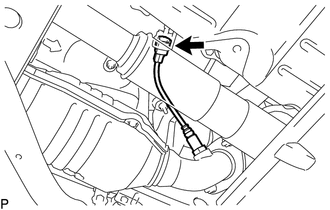
(a) Disengage the 3 clamps to separate the wire harness. |
|
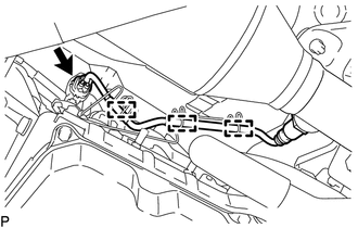
(b) Disconnect the connector.
|
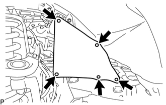
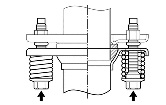
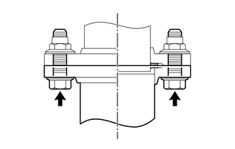
(c) Remove the 2 bolts and 2 compression springs to separate the front exhaust pipe assembly. |
|
|
(d) Remove the 2 nuts and front exhaust pipe assembly. |
|
(e) Remove the 2 gaskets from the front exhaust pipe assembly.
4. REMOVE CENTER NO. 2 FLOOR HEAT INSULATOR SUB-ASSEMBLY (for 4WD)
.gif)
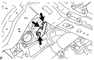
5. REMOVE EXHAUST PIPE STOPPER BRACKET (for 4WD)
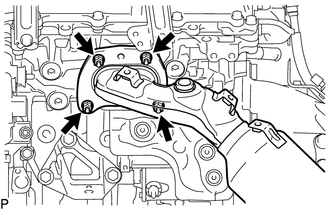
6. REMOVE FRONT NO. 2 EXHAUST PIPE ASSEMBLY
|
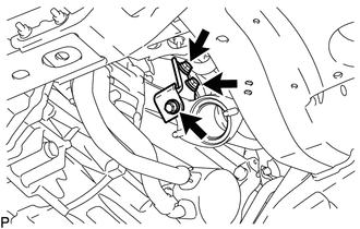
(a) Disconnect the connector. |
|
|
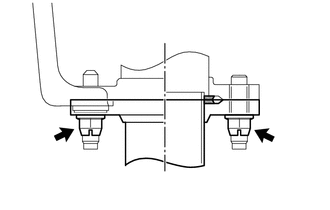
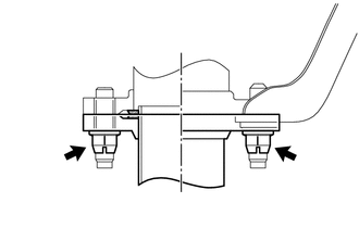
(b) Remove the 2 bolts to separate the front No. 2 exhaust pipe assembly. |
|
|
(c) Remove the 2 nuts to separate the front No. 2 exhaust pipe assembly. |
|
(d) Disconnect the front No. 2 exhaust pipe assembly from the exhaust pipe support.
(e) Remove the 2 gaskets from the front No. 2 exhaust pipe assembly.
7. REMOVE AIR FUEL RATIO SENSOR (for Bank 1 Sensor 1)
8. REMOVE AIR FUEL RATIO SENSOR (for Bank 2 Sensor 1)
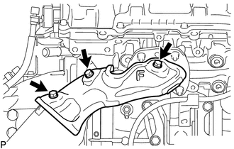
9. REMOVE MANIFOLD STAY
|
(a) Remove the 3 bolts and manifold stay from the transmission assembly and exhaust manifold sub-assembly RH. |
|
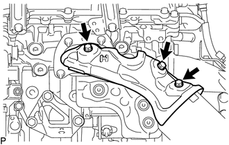
10. REMOVE NO. 1 EXHAUST MANIFOLD HEAT INSULATOR
|
(a) Remove the 3 bolts and No. 1 exhaust manifold heat insulator from the exhaust manifold sub-assembly RH. |
|
11. REMOVE EXHAUST MANIFOLD SUB-ASSEMBLY RH
|
(a) Remove the 4 nuts and exhaust manifold sub-assembly RH from the cylinder head sub-assembly. |
|
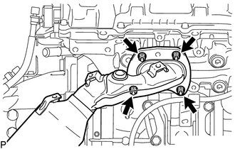
(b) Remove the gasket from the cylinder head sub-assembly.
12. REMOVE NO. 2 MANIFOLD STAY
|
(a) Remove the 3 bolts and No. 2 manifold stay from the transmission assembly and exhaust manifold sub-assembly LH. |
|
13. REMOVE NO. 2 EXHAUST MANIFOLD HEAT INSULATOR
|
(a) Remove the 3 bolts and No. 2 exhaust manifold heat insulator from the exhaust manifold sub-assembly LH. |
|
14. REMOVE EXHAUST MANIFOLD SUB-ASSEMBLY LH
|
(a) Remove the 4 nuts and exhaust manifold sub-assembly LH from the cylinder head LH. |
|
(b) Remove the gasket from the cylinder head LH.
 Installation
INSTALLATION
PROCEDURE
1. INSTALL EXHAUST MANIFOLD SUB-ASSEMBLY LH
(a) Install a new gasket to the cylinder head LH.
NOTICE:
Be careful of the installation direction.
(b) Temporarily install the ...
 Exhaust Pipe
...
Other materials:
Open in One Side of Bus 3 Branch Line
DESCRIPTION
When the CAN bus main lines are normal (no open, short to ground, short to +B
or short between lines) and there is an ECU or sensor on the "Communication Bus
Check" screen that is indicated as not communicating or whose connection status
on the "Communication Bus Ch ...
Parts Location
PARTS LOCATION
ILLUSTRATION
ILLUSTRATION
ILLUSTRATION
ILLUSTRATION
ILLUSTRATION
ILLUSTRATION
ILLUSTRATION
ILLUSTRATION
ILLUSTRATION
...
Installation
INSTALLATION
CAUTION / NOTICE / HINT
HINT:
Use the same procedure for both the LH and RH sides.
The procedure described below is for the LH side.
PROCEDURE
1. INSTALL FOG LIGHT ASSEMBLY
(a) Engage the 2 guides to install the fog light assembly.
(b) Install the screw.
(c) Co ...
