Toyota Tacoma (2015-2018) Service Manual: Transmission Fluid Temperature Sensor "A" Circuit Short To Ground (P071011)
DESCRIPTION
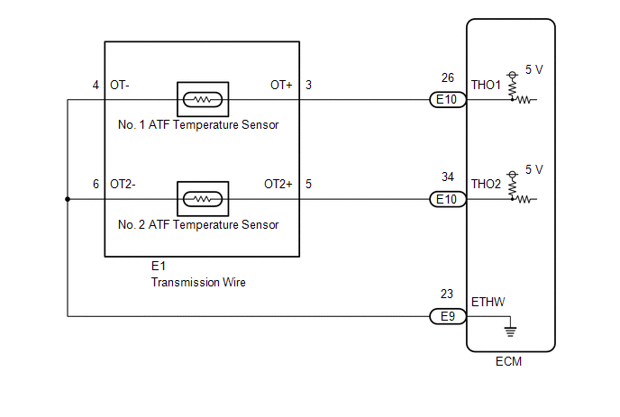
The No. 1 ATF temperature sensor converts the fluid temperature into a resistance value for use by the ECM.
The ECM applies a voltage to the temperature sensor through terminal THO1 of the ECM.
The sensor resistance changes with the ATF temperature. As the temperature becomes higher, the sensor resistance decreases.
One terminal of the sensor is grounded so that the sensor resistance decreases and the voltage goes down as the temperature becomes higher.
The ECM calculates the fluid temperature based on the voltage signal.
|
DTC No. |
DTC Detection Condition |
Trouble Area |
SAE |
|---|---|---|---|
|
P071011 |
The output voltage from the No. 1 ATF temperature sensor is below 0.142 V for 0.5 seconds or more (1 trip detection logic). |
|
P0712 |
MONITOR DESCRIPTION
The No. 1 ATF temperature sensor converts the ATF temperature to an electrical resistance value. Based on the resistance, the ECM determines the ATF temperature and detects a short in the No. 1 ATF temperature sensor circuit. If the resistance value of the No. 1 ATF temperature sensor is below 79 Ω*, the ECM interprets this as a fault in the No. 1 ATF temperature sensor or wiring. The ECM will illuminate the MIL and store the DTC.
*: 150°C (302°F) or higher is indicated regardless of the actual ATF temperature.
HINT:
The ATF temperature can be checked on the Techstream display.
MONITOR STRATEGY
|
Related DTCs |
P0712: ATF temperature sensor/Range check (Low voltage) |
|
Required sensors/Components |
ATF temperature sensor (TFT sensor) |
|
Frequency of operation |
Continuous |
|
Duration |
0.5 sec. |
|
MIL operation |
Immediately |
|
Sequence of operation |
None |
TYPICAL ENABLING CONDITIONS
|
The monitor will run whenever these DTCs are not stored |
None |
|
Battery voltage |
8 V or more |
|
Ignition switch |
ON |
|
Starter |
OFF |
TYPICAL MALFUNCTION THRESHOLDS
|
ATF temperature sensor voltage (ATF temperature) |
Below 0.142 V (Higher than 164°C (327°F)) |
COMPONENT OPERATING RANGE
|
ATF temperature sensor voltage (ATF temperature) |
0.142 V or higher, and 4.915 V or less (-48°C (-54°F) or higher, and 164°C (327°F) or less) |
CONFIRMATION DRIVING PATTERN
HINT:
- After repairs have been completed, clear the DTCs and then check that the vehicle has returned to normal by performing the following All Readiness check procedure.
- When clearing the permanent DTCs, refer to the Clear Permanent DTC procedure
(See page
.gif) ).
).
- Connect the Techstream to the DLC3.
- Turn the ignition switch to ON and turn the Techstream on.
- Clear the DTCs (even if no DTCs are stored, perform the clear DTC procedure).
- Turn the ignition switch off and wait for 2 minutes or more.
- Turn the ignition switch to ON and turn the Techstream on.
- Wait for 3 seconds or more with the ignition switch to ON. [*1]
HINT:
[*1] : Normal judgment procedure.
The normal judgment procedure is used to complete DTC judgment and also used when clearing permanent DTCs.
- Enter the following menus: Powertrain / Transmission / Utility / All Readiness.
- Input the DTC: P071011.
- Check the DTC judgment result.
Techstream Display
Description
NORMAL
- DTC judgment completed
- System normal
ABNORMAL
- DTC judgment completed
- System abnormal
INCOMPLETE
- DTC judgment not completed
- Perform driving pattern after confirming DTC enabling conditions
N/A
- Unable to perform DTC judgment
- Number of DTCs which do not fulfill DTC preconditions has reached ECU memory limit
HINT:
- If the judgment result shows NORMAL, the system is normal.
- If the judgment result shows ABNORMAL, the system has a malfunction.
- If the judgment result shows INCOMPLETE or N/A, perform the normal judgment procedure again.
WIRING DIAGRAM
CAUTION / NOTICE / HINT
NOTICE:
- Perform the universal trip to clear permanent DTCs (See page
).
- Perform registration and/or initialization when parts related to the
automatic transmission are replaced (See page
).
1. DATA LIST
HINT:
Using the Techstream to read the Data List allows the values or states of switches, sensors, actuators and other items to be read without removing any parts. This non-intrusive inspection can be very useful because intermittent conditions or signals may be discovered before parts or wiring is disturbed. Reading the Data List information early in troubleshooting is one way to save diagnostic time.
NOTICE:
In the table below, the values listed under "Normal Condition" are reference values. Do not depend solely on these reference values when deciding whether a part is faulty or not.
(a) Warm up the engine.
(b) Turn the ignition switch off.
(c) Connect the Techstream to the DLC3.
(d) Turn the ignition switch to ON.
(e) Turn the Techstream on.
(f) Enter the following menus: Powertrain / Transmission / Data List.
(g) According to the display on the Techstream, read the Data List.
Transmission|
Tester Display |
Measurement Item/Range |
Normal Condition |
Diagnostic Note |
|---|---|---|---|
|
A/T Oil Temperature No. 1 |
No. 1 ATF temperature sensor value/ Min.: -40°C (-40°F) Max.: 150°C (302°F) |
|
If the value -40°C (-40°F) or 150°C (302°F), No. 1 ATF temperature sensor circuit is open or shorted. |
HINT:
When DTC P071011 is output and the Techstream indicates 150°C (302°F) or higher, there is a short circuit.
When DTC P071015 is output and the Techstream indicates -40°C (-40°F), there is an open circuit.
Check the temperature displayed on the Techstream in order to check if a malfunction exists.
|
Temperature Displayed |
Malfunction |
|---|---|
|
-40°C (-40°F) |
Open circuit |
|
150°C (302°F) or higher |
Short circuit |
PROCEDURE
|
1. |
INSPECT NO. 1 ATF TEMPERATURE SENSOR (TRANSMISSION WIRE) |
|
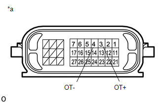
(a) Disconnect the E1 transmission wire connector. |
|
(b) Measure the resistance according to the value(s) in the table below.
Standard Resistance:
|
Tester Connection |
Condition |
Specified Condition |
|---|---|---|
|
3 (OT+) - 4 (OT-) |
Always |
79 Ω to 156 kΩ |
|
3 (OT+) or 4 (OT-) - Body ground and other terminals |
Always |
10 kΩ or higher |
HINT:
If the resistance is out of the specified range at any of the ATF temperatures shown in the table below, the driveability of the vehicle may decrease.
|
ATF Temperature |
Specified Condition |
|
10°C (50°F) |
5 to 8 kΩ |
|
25°C (77°F) |
2.5 to 4.5 kΩ |
|
110°C (230°F) |
0.22 to 0.28 kΩ |
|
*a |
Component without harness connected (Transmission Wire) |
| NG | .gif) |
REPLACE NO. 1 ATF TEMPERATURE SENSOR (TRANSMISSION WIRE) |
|
.gif)
|
2. |
CHECK HARNESS AND CONNECTOR (TRANSMISSION WIRE - ECM) |
|
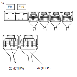
(a) Disconnect the ECM connector. |
|
(b) Measure the resistance according to the value(s) in the table below.
Standard Resistance:
|
Tester Connection |
Condition |
Specified Condition |
|---|---|---|
|
E10-26 (THO1) - E9-23 (ETHW) |
Always |
79 Ω to 156 kΩ |
|
E10-26 (THO1) - Body ground |
Always |
10 kΩ or higher |
|
*a |
Rear view of wire harness connector (to ECM) |
| OK | |
REPLACE ECM |
| NG | |
REPAIR OR REPLACE HARNESS OR CONNECTOR |
 Brake Switch "B" Circuit Short to Battery (P070312)
DESCRIPTION
The purpose of this circuit is to prevent the engine from stalling while driving
in lock-up when the brakes are suddenly applied.
When the brake pedal is depressed, this switch sends a ...
 Torque Converter Clutch Circuit Short to Ground (P074011)
DESCRIPTION
Shift solenoid valve SL is turned on and off by signals from the ECM to control
the hydraulic pressure acting on the lock-up relay valve, which then controls operation
of the lock-up ...
Other materials:
Inspection
INSPECTION
PROCEDURE
1. INSPECT REAR NO. 2 POWER WINDOW REGULATOR SWITCH ASSEMBLY
*a
Component without harness connected
(Rear No. 2 Power Window Regulator Switch Assembly)
*b
Pull (Close)
*c
Push (Open)
...
Hydraulic Test
HYDRAULIC TEST
1. PERFORM HYDRAULIC TEST
(a) Measure the line pressure.
CAUTION:
The line pressure test should always be performed with at least 2 people. One
person should observe the condition of the wheels and wheel chocks while the other
is performing the test.
NOTICE:
Perform ...
Problem Symptoms Table
PROBLEM SYMPTOMS TABLE
NOTICE:
After replacing the stereo component tuner assembly of vehicles subscribed to
pay-type satellite radio broadcasts, XM radio ID registration is necessary (w/ SDARS
System).
HINT:
Use the table below to help determine the cause of problem symptoms.
If ...
