Toyota Tacoma (2005–2015) Owners Manual: Floor mat
Use only floor mats designed specifically for vehicles of the same model and model year as your vehicle. Fix them securely in place onto the carpet.
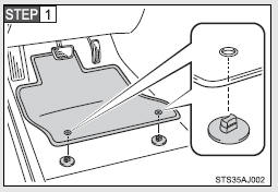
Insert the retaining hooks (clips) into the floor mat eyelets.
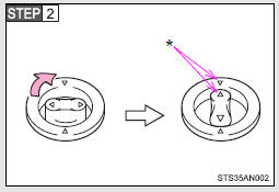
Turn the upper knob of each retaining hook (clip) to secure the floor mats in place.
*: Always align the  marks.
The shape of the retaining hooks (clips) may differ from that shown in the illustration.
CAUTION
Observe the following precautions.
Failure to do so may cause the driver’s floor mat to slip, possibly interfering with the pedals while driving. An unexpectedly high speed may result or it may become difficult to stop the vehicle, leading to a serious accident.
■When installing the driver‚Äôs floor mat
●Do not use floor mats designed for other models or different model year vehicles, even if they are Toyota Genuine floor mats.
●Only use floor mats designed for the driver‚Äôs seat.
●Always install the floor mat securely using the retaining hooks (clips) provided.
●Do not use two or more floor mats on top of each other.
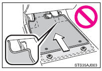
●Do not place the floor mat bottom-side up or upside-down.
■Before driving
●Check that the floor mat is securely fixed in the correct place with all the provided retaining hooks (clips). Be especially careful to perform this check after cleaning the floor.
●With the engine stopped and the shift lever in P (automatic transmission) or N (manual transmission), fully depress each pedal to the floor to make sure it does not interfere with the floor mat.
 Seatback table
Front passenger’s seatback can be used as a temporary table only when the
vehicle is stopped.
Fold down the front passenger’s seat to use the seatback table.
CAUTION
■Caution while dr ...
 Luggage compartment features
Behind the rear seat (Double
Cab models only)
1.Cargo net hooks (vehicles with sub woofer)
2.Grocery bag hooks
3.Flashlight holder
4.Storage boxes
Deck
1. Auxiliary boxes
2. Tie-down cl ...
Other materials:
Data List / Active Test
DATA LIST / ACTIVE TEST
1. DATA LIST
HINT:
Using the Techstream to read the Data List allows the values or states of switches,
sensors, actuators and other items to be read without removing any parts. This non-intrusive
inspection can be very useful because intermittent conditions or signals ...
Precaution
PRECAUTION
1. IGNITION SWITCH EXPRESSION
HINT:
The type of ignition switch used on this model differs depending on the specifications
of the vehicle. The expressions listed in the table below are used in this section.
Expression
Ignition Switch (Position)
Engin ...
Fuel Tank Cap
Inspection
INSPECTION
PROCEDURE
1. INSPECT FUEL TANK CAP ASSEMBLY
(a) Check the appearance of the fuel tank cap assembly.
(1) Check that there is no deformation or damage to the fuel tank cap assembly
or fuel tank cap gasket.
*1
Fuel Tank Cap Gasket
If the ...
