Toyota Tacoma (2015-2018) Service Manual: Installation
INSTALLATION
CAUTION / NOTICE / HINT
HINT:
- Use the same procedures for the RH side and LH side.
- The procedures listed below are for the LH side.
- When installing a roof drip side moulding clip, heat the vehicle body and clip using a heat light.
- When installing the moulding, heat the vehicle body and moulding using a heat light.
|
Item |
Temperature |
|---|---|
|
Vehicle Body |
40 to 60°C (104 to 140°F) |
|
Moulding |
20 to 30°C (68 to 86°F) |
|
Clip |
20 to 30°C (68 to 86°F) |
NOTICE:
Do not heat the vehicle body, moulding and roof drip side moulding clip excessively.
PROCEDURE
1. INSTALL ROOF DRIP SIDE FINISH MOULDING CLIP
HINT:
Perform this procedure only when installing new roof drip side moulding clips.
(a) Using a heat light, heat the roof drip side moulding clip installation areas on the vehicle body.
(b) Remove the double-sided tape from the vehicle body.
(c) Wipe off any tape adhesive residue with cleaner.
(d) Using a heat light, heat the roof drip side moulding clips.
(e) Remove the peeling paper from the face of the roof drip side moulding clips.
HINT:
After removing the peeling paper, keep the exposed adhesive free from foreign matter.
(f) Install the roof drip side moulding clips in the positions shown in the illustration.
HINT:
Press the clips firmly to install them.
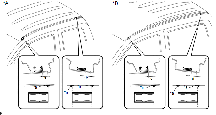 Text in Illustration
|
*A |
for Access Cab |
*B |
for Double Cab |
|
*a |
Alignment Mark |
- |
- |
|
Dimension |
Measurement |
Dimension |
Measurement |
|---|---|---|---|
|
a |
6.2 mm (0.244 in.) |
b |
5.8 mm (0.228 in.) |
|
c |
6.2 mm (0.244 in.) |
d |
5.8 mm (0.228 in.) |
2. INSTALL ROOF DRIP SIDE FINISH MOULDING
(a) for Double Cab:
(1) Clean the vehicle body surface.
- Using a heat light, heat the vehicle body surface.
- Remove the double-sided tape from the vehicle body.
- Wipe off any tape adhesive residue with cleaner.
(b) for Double Cab:
(1) Using a heat light, heat the vehicle body and a new roof drip side finish moulding.
(2) Remove the peeling paper from the face of the roof drip side finish moulding.
HINT:
After removing the peeling paper, keep the exposed adhesive free from foreign matter.
|
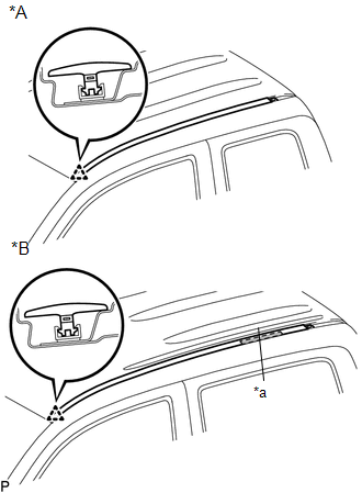
(c) Engage the clip to install the roof drip side finish moulding. Text in Illustration
HINT: Press the roof drip side finish moulding firmly to install it. |
|
3. INSTALL ROOF DRIP SIDE REAR FINISH MOULDING
(a) Clean the vehicle body surface.
(1) Using a heat light, heat the vehicle body surface.
(2) Remove the double-sided tape from the vehicle body.
(3) Wipe off any tape adhesive residue with cleaner.
(b) Install the moulding.
(1) Using a heat light, heat the vehicle body and a new roof drip side rear finish moulding.
(2) Remove the peeling paper from the face of the roof drip side rear finish moulding.
HINT:
After removing the peeling paper, keep the exposed adhesive free from foreign matter.
|
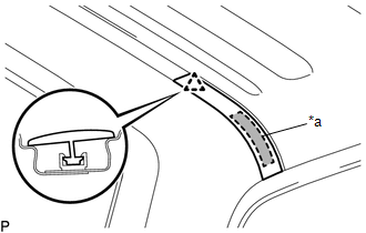
(3) Attach the clip to install the roof drip side rear finish moulding. Text in Illustration
HINT: Press the roof drip side rear finish moulding firmly to install it. |
|
 Removal
REMOVAL
CAUTION / NOTICE / HINT
HINT:
Use the same procedures for the RH side and LH side.
The procedures listed below are for the LH side.
When removing the moulding, heat the vehi ...
 Side Moulding
Components
COMPONENTS
ILLUSTRATION
ILLUSTRATION
Removal
REMOVAL
CAUTION / NOTICE / HINT
HINT:
Use the same procedure for the RH side and LH side.
The following procedure is ...
Other materials:
Monitor Drive Pattern
MONITOR DRIVE PATTERN
1. TEST MONITOR DRIVE PATTERN FOR ECT
CAUTION:
Perform this drive pattern on a level surface and strictly observe the posted
speed limits and traffic laws while driving.
HINT:
Performing this drive pattern is one method to simulate the ECM (ECT) malfunction
detection c ...
Precaution
PRECAUTION
1. IGNITION SWITCH EXPRESSION
(a) The type of ignition switch used on this model differs depending on the specifications
of the vehicle. The expressions listed in the table below are used in this section.
Expression
Ignition Switch (Position)
Engine S ...
Brake Warning Light Remains ON
DESCRIPTION
The skid control ECU (brake actuator assembly) is connected to the combination
meter assembly via CAN communication.
If any of the following is detected, the brake warning light remains on:
The skid control ECU (brake actuator assembly) connector is disconnected
from the ...
