Toyota Tacoma (2015-2018) Service Manual: Hazard Warning Switch Circuit
DESCRIPTION
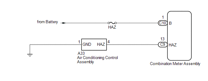
The combination meter assembly receives information signals from the telltale light assembly (hazard warning signal switch).
WIRING DIAGRAM
CAUTION / NOTICE / HINT
NOTICE:
Inspect the fuses for circuits related to this system before performing the following inspection procedure.
PROCEDURE
|
1. |
READ VALUE USING TECHSTREAM (HAZARD FLASHER SWITCH) |
(a) Connect the Techstream to the DLC3.
(b) Turn the ignition switch to ON.
(c) Turn the Techstream on.
(d) Enter the following menus: Body Electrical / Combination Meter / Data List.
(e) According to the display on the Techstream, read the Data List.
Combination Meter|
Tester Display |
Measurement Item/Range |
Normal Condition |
Diagnostic Note |
|---|---|---|---|
|
Hazard Flasher Switch |
Hazard warning signal switch / OFF or ON |
OFF: Hazard warning signal switch off ON: Hazard warning signal switch on |
- |
OK:
Normal conditions listed above are displayed.
| OK | .gif) |
PROCEED TO NEXT SUSPECTED AREA SHOWN IN PROBLEM SYMPTOMS TABLE |
|
.gif)
|
2. |
CHECK HARNESS AND CONNECTOR (COMBINATION METER ASSEMBLY - BATTERY) |
|
(a) Disconnect the combination meter assembly connector. |
|
(b) Measure the voltage according to the value(s) in the table below.
Standard Voltage:
|
Tester Connection |
Condition |
Specified Condition |
|---|---|---|
|
C10-1 (B) - Body Ground |
Always |
11 to 14 V |
|
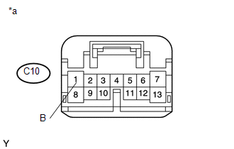
*a |
Front view of wire harness connector (to Combination Meter Assembly) |
| NG | |
REPAIR OR REPLACE HARNESS OR CONNECTOR |
|
|
3. |
CHECK HARNESS AND CONNECTOR (AIR CONDITIONING CONTROL ASSEMBLY - COMBINATION METER ASSEMBLY) |
(a) Disconnect the A33 air conditioning control assembly connector.
(b) Disconnect the C9 combination meter assembly connector.
(c) Measure the resistance according to the value(s) in the table below.
Standard Resistance:
|
Tester Connection |
Condition |
Specified Condition |
|---|---|---|
|
A33-4 (HAZ) - C9-13 (HAZ) |
Always |
Below 1 Ω |
|
A33-1 (GND) - Body Ground |
Always |
Below 1 Ω |
|
A33-4 (HAZ) - Body ground |
Always |
10 kΩ or higher |
| NG | |
REPAIR OR REPLACE HARNESS OR CONNECTOR |
|
|
4. |
REPLACE AIR CONDITIONING CONTROL ASSEMBLY (HAZARD WARNING SIGNAL SWITCH) |
(a) Replace the air conditioning control assembly (hazard warning signal switch)
(See page .gif) ).
).
|
|
5. |
READ VALUE USING TECHSTREAM (HAZARD FLASHER SWITCH) |
(a) Connect the Techstream to the DLC3.
(b) Turn the ignition switch to ON.
(c) Turn the Techstream on.
(d) Enter the following menus: Body Electrical / Combination Meter / Data List.
(e) According to the display on the Techstream, read the Data List.
Combination Meter|
Tester Display |
Measurement Item/Range |
Normal Condition |
Diagnostic Note |
|---|---|---|---|
|
Hazard Flasher Switch |
Hazard warning signal switch / OFF or ON |
OFF: Hazard warning signal switch off ON: Hazard warning signal switch on |
- |
OK:
Normal conditions listed above are displayed.
| OK | |
END (AIR CONDITIONING CONTROL ASSEMBLY (HAZARD WARNING SIGNAL SWITCH) WAS DEFECTIVE) |
| NG | |
REPLACE COMBINATION METER ASSEMBLY |
 Front Fog Light Circuit
DESCRIPTION
The main body ECU (multiplex network body ECU) controls the front fog lights.
WIRING DIAGRAM
CAUTION / NOTICE / HINT
NOTICE:
Inspect the fuses for circuits related to this s ...
 Interior Light Auto Cut Circuit
DESCRIPTION
When the battery saving control operates, the main body ECU (multiplex network
body ECU) controls the operation of the DOME CUT relay, that is built in to the
driver side junction blo ...
Other materials:
Neutral Position Switch
Components
COMPONENTS
ILLUSTRATION
*1
NEUTRAL POSITION SWITCH
*2
GASKET
N*m (kgf*cm, ft.*lbf): Specified torque
â—Ź
Non-reusable part
Installation
INSTALLATION
PROCEDURE
1. INSTALL NEUTR ...
Daytime Running Light Relay Circuit
DESCRIPTION
The main body ECU (multiplex network body ECU) controls the daytime running lights.
WIRING DIAGRAM
CAUTION / NOTICE / HINT
NOTICE:
Inspect the fuses for circuits related to this system before performing
the following inspection procedure.
If the main body ECU (mult ...
Electrical Key Oscillator(for Rear Floor)
Components
COMPONENTS
ILLUSTRATION
Installation
INSTALLATION
PROCEDURE
1. INSTALL NO. 2 INDOOR ELECTRICAL KEY ANTENNA ASSEMBLY
(a) Engage the clamp to install the No. 2 indoor electrical key antenna assembly.
(b) Connect the connector.
2. INSTALL REAR CONSOLE BOX ASSEMBLY
(See page ...
