Toyota Tacoma (2015-2018) Service Manual: Removal
REMOVAL
CAUTION / NOTICE / HINT
HINT:
- Use the same procedures for the RH side and LH side.
- The procedures listed below are for the LH side.
- When removing the moulding, heat the vehicle body and moulding using a heat light.
|
Item |
Temperature |
|---|---|
|
Vehicle Body |
40 to 60°C (104 to 140°F) |
|
Moulding |
20 to 30°C (68 to 86°F) |
NOTICE:
Do not heat the vehicle body, moulding and clip excessively.
PROCEDURE
1. REMOVE ROOF DRIP SIDE REAR FINISH MOULDING
|
(a) Put protective tape around the roof drip side rear finish moulding. Text in Illustration
|
|
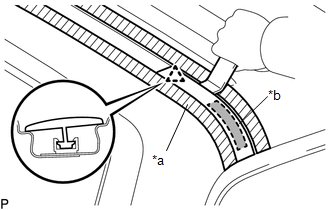
(b) Using a heat light, heat the roof drip side rear finish moulding.
NOTICE:
Do not heat the moulding and vehicle body excessively.
(c) Using a moulding remover D, disengage the clip, and peel off the double-sided tape to remove the roof drip side rear finish moulding.
NOTICE:
- Do not remove the roof drip side finish moulding clip from the vehicle body.
- If the clip is damaged or removed accidentally, replace it.
2. REMOVE ROOF DRIP SIDE FINISH MOULDING
|
(a) Put protective tape around the roof drip side finish moulding. Text in Illustration
|
|
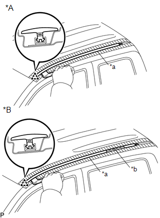
(b) for Double Cab:
(1) Using a heat light, heat the roof drip side finish moulding.
NOTICE:
Do not heat the moulding and vehicle body excessively.
(c) Using a moulding remover D, disengage the clip, and peel off the double-sided tape to remove the roof drip side finish moulding.
NOTICE:
- Do not remove the roof drip side finish moulding clip from the vehicle body.
- If the clip is damaged or removed accidentally, replace it.
(d) Remove the protective tape.
 Components
COMPONENTS
ILLUSTRATION
ILLUSTRATION
...
 Installation
INSTALLATION
CAUTION / NOTICE / HINT
HINT:
Use the same procedures for the RH side and LH side.
The procedures listed below are for the LH side.
When installing a roof drip side mou ...
Other materials:
Network Gateway Ecu
Components
COMPONENTS
ILLUSTRATION
Installation
INSTALLATION
PROCEDURE
1. INSTALL NETWORK GATEWAY ECU
(a) Install the network gateway ECU with the bolt.
Torque:
3.0 N·m {31 kgf·cm, 27 in·lbf}
(b) Connect the connector.
2. INSTALL LOWER INSTRUMENT PANEL ASSEMBLY
(See page )
R ...
Ignition Switch
Components
COMPONENTS
ILLUSTRATION
Removal
REMOVAL
PROCEDURE
1. REMOVE LOWER STEERING COLUMN COVER
(a) Remove the 2 screws.
(b) Disengage the 2 claws and remove the lower steering column cover.
2. REMOVE IGNITION OR STARTER SWITCH ASSEMBLY
(a) Disconnect the connector.
(b) Disen ...
USB Media Malfunction (B1585)
DESCRIPTION
This DTC is stored when a malfunction occurs in a connected device.
DTC No.
DTC Detection Condition
Trouble Area
B1585
USB Device Malfunction
Non mass-storage class or incompatible protocol USB device
...
