Toyota Tacoma (2015-2018) Service Manual: Removal
REMOVAL
CAUTION / NOTICE / HINT
NOTICE:
- When replacing the forward recognition camera, replace it with a new one.
- Do not touch the camera lens or the front windshield glass in front of the camera.
- If the forward recognition camera has been struck or dropped, replace it with a new one.
- When replacing the windshield glass of a vehicle equipped with a forward recognition camera, make sure to use a Toyota genuine part. If a non-Toyota genuine part is used, the forward recognition camera may not be able to be installed due to a missing bracket. Also, the dynamic radar cruise control system, forward recognition camera system, lane departure alert system, pre-collision system may not operate properly due to a difference in the transmissivity or black ceramic border.
- Do not touch the internal components of the forward recognition with heater hood sub-assembly or press on the heater when working on the forward recognition with heater hood sub-assembly.
PROCEDURE
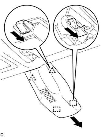
1. REMOVE NO. 1 FORWARD RECOGNITION COVER
|
(a) Disengage the 2 clips and 2 guides to remove the No. 1 forward recognition cover as shown in the illustration. NOTICE: When removing, press the cover parallel to the windshield glass surface and remove. |
|
2. REMOVE FORWARD RECOGNITION LATCH
|
(a) Disengage the 2 claws in the direction indicated by the arrow (1) in the illustration. |
|
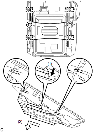
(b) Disengage the 4 guides in the direction indicated by the arrow (2) in the illustration to remove the forward recognition latch.
3. REMOVE FORWARD RECOGNITION CAMERA
NOTICE:
If the forward recognition camera has been struck or dropped, replace it with a new one.
|
(a) Disconnect the connector. NOTICE: Do not pull the harness forcibly when disconnecting the connector. |
|
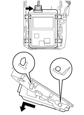
(b) Disengage the 4 guides to remove the forward recognition camera as shown in the illustration.
NOTICE:
- Do not apply excessive force.
- If the forward recognition camera bracket is deformed or damaged, replace it together with the windshield glass.
 Components
COMPONENTS
ILLUSTRATION
*1
FORWARD RECOGNITION CAMERA
*2
FORWARD RECOGNITION LATCH
*3
NO. 1 FORWARD RECOGNITION COVER
...
 Before Starting Adjustment
BEFORE STARTING ADJUSTMENT
CAUTION / NOTICE / HINT
NOTICE:
When replacing the windshield glass of a vehicle equipped with a forward recognition
camera, make sure to use a Toyota genuine part. If ...
Other materials:
On-vehicle Inspection
ON-VEHICLE INSPECTION
PROCEDURE
1. INSPECT LOWER NO. 1 INSTRUMENT PANEL AIRBAG ASSEMBLY (for Vehicle not Involved
in Collision)
(a) Perform a diagnostic system check (See page
).
(b) With the lower No. 1 instrument panel airbag assembly ...
Removal
REMOVAL
PROCEDURE
1. REMOVE SLIDING ROOF SIDE GARNISH LH
(a) Fully open the sunshade trim sub-assembly.
(b) Remove the sliding roof side garnish LH.
2. REMOVE SLIDING ROOF SIDE GARNISH RH
HINT:
Use the same procedure as for the LH side.
3. ...
LVDS Signal Malfunction (from Extension Module) (B1532)
DESCRIPTION
The stereo component tuner assembly and the radio and display receiver assembly
are connected by an LVDS communication line.
This DTC is stored when an LVDS communication error occurs between the stereo
component tuner assembly and the radio and display receiver assembly.
...
