Toyota Tacoma (2015-2018) Service Manual: Side Moulding
Components
COMPONENTS
ILLUSTRATION
ILLUSTRATION
Removal
REMOVAL
CAUTION / NOTICE / HINT
HINT:
- Use the same procedure for the RH side and LH side.
- The following procedure is for the LH side.
- When removing the lower No. 2 side panel moulding, heat the vehicle body and lower No. 2 side panel moulding using a heat light.
|
Item |
Temperature |
|---|---|
|
Vehicle Body |
40 to 60°C (104 to 140°F) |
|
Lower No. 2 Side Panel Moulding |
20 to 30°C (68 to 86°F) |
NOTICE:
Do not heat the vehicle body or lower No. 2 side panel moulding excessively.
PROCEDURE
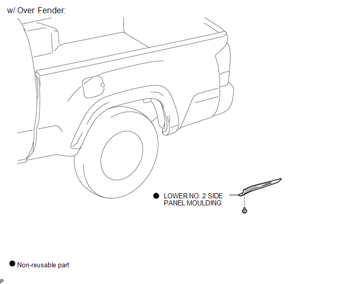
1. REMOVE LOWER NO. 2 SIDE PANEL MOULDING (w/ Over Fender)
(a) Using a heat light, heat the lower No. 2 side panel moulding.
|
(b) Remove the screw. Text in Illustration
|
|
(c) Disengage the 2 claws, and peel off the double-sided tape to remove the lower No. 2 side panel moulding.
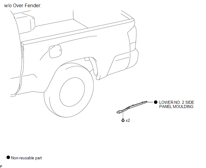
2. REMOVE LOWER NO. 2 SIDE PANEL MOULDING (w/o Over Fender)
(a) Using a heat light, heat the lower No. 2 side panel moulding.
|
(b) Remove the 2 screws. Text in Illustration
|
|
(c) Disengage the 2 claws, and peel off the double-sided tape to remove the lower No. 2 side panel moulding.
Installation
INSTALLATION
CAUTION / NOTICE / HINT
HINT:
- Use the same procedure for the RH side and LH side.
- The following procedure is for the LH side.
- When installing the lower No. 2 side panel moulding, heat the vehicle body and lower No. 2 side panel moulding using a heat light.
PROCEDURE
1. INSTALL LOWER NO. 2 SIDE PANEL MOULDING (w/ Over Fender)
(a) Clean the vehicle body surface.
(1) Using a heat light, heat the vehicle body surface.
(2) Remove the double-sided tape from the vehicle body.
(3) Clean off any tape adhesive residue with cleaner.
(b) Install a new lower No. 2 side panel moulding.
(1) Using a heat light, heat the vehicle body and a new lower No. 2 side panel moulding.
(2) Remove the release paper from the lower No. 2 side panel moulding.
HINT:
After removing the release paper, keep the exposed adhesive free from foreign matter.
|
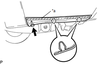
(3) Engage the claws to install the lower No. 2 side panel moulding. Text in Illustration
|
|
.png)
(4) Install the screw.
2. INSTALL LOWER NO. 2 SIDE PANEL MOULDING (w/o Over Fender)
(a) Clean the vehicle body surface.
(1) Using a heat light, heat the vehicle body surface.
(2) Remove the double-sided tape from the vehicle body.
(3) Clean off any tape adhesive residue with cleaner.
(b) Install a new lower No. 2 side panel moulding.
(1) Using a heat light, heat the vehicle body and a new lower No. 2 side panel moulding.
(2) Remove the release paper from the lower No. 2 side panel moulding.
HINT:
After removing the release paper, keep the exposed adhesive free from foreign matter.
|
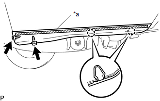
(3) Engage the claws to install the lower No. 2 side panel moulding. Text in Illustration
|
|
.png)
(4) Install the 2 screws.
 Installation
INSTALLATION
CAUTION / NOTICE / HINT
HINT:
Use the same procedures for the RH side and LH side.
The procedures listed below are for the LH side.
When installing a roof drip side mou ...
 Tail Gate Protector
Components
COMPONENTS
ILLUSTRATION
Removal
REMOVAL
PROCEDURE
1. REMOVE TAIL GATE PROTECTOR
(a) Using a T30 "TORX" socket wrench, remove the 8 screws.
...
Other materials:
Removal
REMOVAL
PROCEDURE
1. REMOVE SHIFT LEVER KNOB SUB-ASSEMBLY (for Automatic Transmission)
(a) Using a molding remover A, disengage the 2 claws to separate the
shifting hole cover sub-assembly.
(b) Rotate the shift lever knob sub-as ...
Crawl Indicator Light Remains ON
DESCRIPTION
When CRAWL starts after operating the CRAWL switch (drive monitor switch), the
CRAWL indicator light turns on. While CRAWL is in the process of stopping, the CRAWL
indicator light begins blinking. When CRAWL totally stops, the CRAWL indicator light
turns off.
WIRING DIAGRAM
CA ...
Problem Symptoms Table
PROBLEM SYMPTOMS TABLE
HINT:
Use the table below to help determine the cause of problem symptoms.
If multiple suspected areas are listed, the potential causes of the symptoms
are listed in order of probability in the "Suspected Area" column of the
table. Check each sy ...
