Toyota Tacoma (2015-2018) Service Manual: Installation
INSTALLATION
PROCEDURE
1. INSTALL REAR DIFFERENTIAL DRIVE PINION BEARING SPACER
(a) Install a new front differential drive pinion bearing spacer.
HINT:
Make sure the front differential drive pinion bearing spacer is installed correctly.
2. INSTALL DIFFERENTIAL OIL STORAGE RING
(a) Using a brass bar and hammer, tap in a new differential oil storage.
HINT:
Be careful not to damage the differential oil storage ring.
3. INSTALL REAR DRIVE PINION FRONT TAPERED ROLLER BEARING
(a) Using SST and a hammer, install the front bearing outer race.
(b) Install the front bearing.
SST: 09316-60011
09316-00011
09316-00021
4. INSTALL REAR DIFFERENTIAL DRIVE PINION OIL SLINGER
(a) Install the rear differential drive pinion oil slinger to the differential drive pinion.
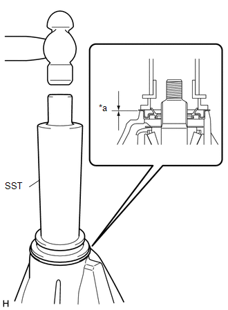
5. INSTALL REAR DIFFERENTIAL CARRIER OIL SEAL
(a) for BD20:
|
(1) Using SST and a hammer, install a new oil seal. Text in Illustration
SST: 09554-30011 Oil seal drive in depth: 0.4 to 1.0 mm (0.016 to 0.039 in.) |
|
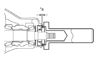
(b) for BD22:
|
(1) Using SST and a hammer, install a new oil seal. Text in Illustration
SST: 09316-60011 09316-00031 SST: 09502-12010 Oil seal drive in depth: 0.0 to 0.3 mm (0.000 to 0.012 in.) |
|
(c) Coat oil seal lip with MP grease.
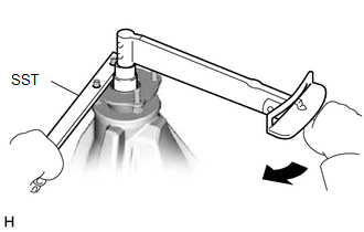
6. INSTALL REAR DRIVE PINION COMPANION FLANGE SUB-ASSEMBLY
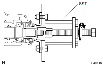
(a) Using SST, install the companion flange.
(b) Coat the threads of a new nut with hypoid gear oil LSD.
SST: 09950-30012
09951-03010
09953-03010
09954-03010
09955-03030
09956-03030
(c) for BD20:
|
(1) Using SST to hold the companion flange, tighten the nut. SST: 09330-00021 Torque: 370 N·m {3773 kgf·cm, 273 ft·lbf} |
|
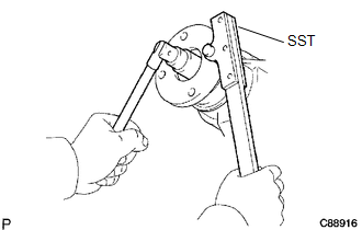
(d) for BD22:
|
(1) Using SST to hold the companion flange, tighten the nut. SST: 09330-00021 Torque: 457 N·m {4660 kgf·cm, 337 ft·lbf} |
|
7. INSPECT TOTAL PRELOAD
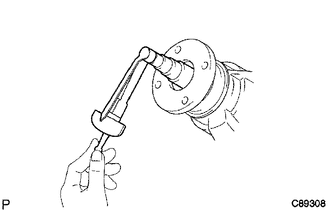
(a) Using a torque wrench, measure the preload of backlash between the drive pinion and ring rear.
Standard Total Preload (for BD20):
|
Reduction Ratio |
Bearing |
Preload |
|---|---|---|
|
3.909 |
New bearing |
1.45 to 2.73 N*m 15 to 27 kgf*cm, 13 to 24 in.*lbf) |
|
Reused bearing |
1.45 to 2.50 N*m 15 to 25 kgf*cm, 12 to 22 in.*lbf) |
|
|
4.300 |
New bearing |
1.41 to 2.66 N*m (15 to 27 kgf*cm, 13 to 23 in.*lbf) |
|
Reused bearing |
1.42 to 2.45 N*m (15 to 24 kgf*cm, 13 to 21 in.*lbf) |
Standard Total Preload (for BD22A,BD22AN):
|
Reduction Ratio |
Bearing |
Preload |
|---|---|---|
|
3.909 |
New bearing |
1.87 to 4.15 N*m 20 to 42 kgf*cm, 17 to 36 in.*lbf) |
|
Reused bearing |
1.90 to 3.97 N*m 20 to 40 kgf*cm, 17 to 35 in.*lbf) |
|
|
4.300 |
New bearing |
1.85 to 4.10 N*m (19 to 42 kgf*cm, 17 to 36 in.*lbf) |
|
Reused bearing |
1.88 to 3.92 N*m (20 to 39 kgf*cm, 17 to 34 in.*lbf) |
If necessary, disassemble and inspect the differential assembly.
8. STAKE REAR DRIVE PINION NUT
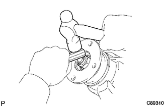
(a) Using a chisel and a hammer, stake the nut.
9. INSTALL PROPELLER WITH CENTER BEARING SHAFT ASSEMBLY (for 2WD)
.gif)
10. INSTALL PROPELLER WITH CENTER BEARING SHAFT ASSEMBLY (for 4WD)
11. ADD DIFFERENTIAL OIL
12. INSPECT DIFFERENTIAL OIL
13. INSPECT FOR DIFFERENTIAL OIL LEAKAGE
 Removal
REMOVAL
PROCEDURE
1. DRAIN DIFFERENTIAL OIL
2. REMOVE PROPELLER WITH CENTER BEARING SHAFT ASSEMBLY (for 2WD)
3. REMOVE PROPELLER WITH CENTER BEARING SHAFT ASSEMBLY (for 4WD)
4. REMOVE REAR ...
 Differential Oil
Adjustment
ADJUSTMENT
PROCEDURE
1. INSPECT DIFFERENTIAL OIL
(a) Stop the vehicle on a level place.
(b) Remove the differential filler plug and gasket.
(c) Check that the oil level is within ...
Other materials:
Removal
REMOVAL
CAUTION / NOTICE / HINT
NOTICE:
Release the vacuum from booster by depressing the brake pedal several times.
Then remove the brake master cylinder from brake booster.
PROCEDURE
1. PRECAUTION
NOTICE:
After turning the ignition switch off, waiting time may be required before disconnect ...
Installation
INSTALLATION
PROCEDURE
1. INSTALL TRANSMISSION WIRE
(a) Coat 2 new O-rings with ATF, and install them to the 2 temperature sensors.
(b) Coat a new O-ring with ATF, and install it to the transmission wire.
(c) Install the transmission wire to the automatic transmission case sub-assembly
with t ...
Sending Malfunction (Navigation to APGS) (U0073,U0100,U0140,U0155)
DESCRIPTION
These DTCs are stored when a malfunction occurs in the CAN communication circuit.
DTC No.
DTC Detection Condition
Trouble Area
U0073
CAN bus connection error
CAN communication system
U0100
...
