Toyota Tacoma (2015-2018) Service Manual: On-vehicle Inspection
ON-VEHICLE INSPECTION
PROCEDURE
1. INSPECT WINDSHIELD WIPER SWITCH ASSEMBLY (w/ Intermittent function)
(a) Remove the steering column cover.
(b) Check the front wiper intermittent operation.
 Text in Illustration
|
*a |
Component with harness connected (Windshield Wiper Switch Assembly) |
(1) Turn the ignition switch on (IG).
(2) Turn the wiper switch to the INT position.
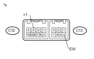
(3) Operate the intermittent wiper and check the voltage between terminals C12-3 (+1) and C13-4 (EW).
HINT:
Measure the voltage on the wire harness side with the connector connected.
OK:
Voltage changes as shown in the illustration.
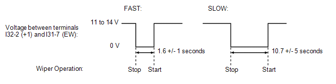
If the result is not as specified, replace the windshield wiper switch assembly.
(c) Check the front washer operation.
 Text in Illustration
|
*a |
Component with harness connected (Windshield Wiper Switch Assembly) |
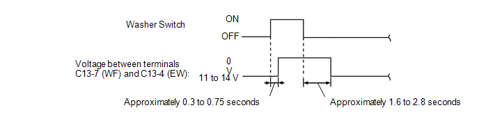
(1) Turn the ignition switch on (IG).
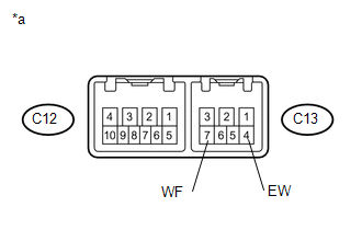
(2) Turn the washer switch on and off, and check the voltage between terminals C13-7 (WF) and C13-4 (EW).
HINT:
Measure the voltage on the wire harness side with the connector connected.
OK:
Voltage changes as shown in the illustration.
(3) Install the steering column cover.
 Components
COMPONENTS
ILLUSTRATION
...
 Removal
REMOVAL
PROCEDURE
1. REMOVE LOWER STEERING COLUMN COVER
2. REMOVE UPPER STEERING COLUMN COVER
3. REMOVE WINDSHIELD WIPER SWITCH ASSEMBLY
(a) Disconnect the 2 connectors.
Tex ...
Other materials:
Front Occupant Classification Sensor LH Circuit Malfunction (B1780)
DESCRIPTION
The occupant classification sensor front LH circuit consists of the occupant
detection ECU and the occupant classification sensor front LH.
DTC B1780 is set when a malfunction is detected in the occupant classification
sensor front LH circuit.
DTC No.
DTC Det ...
Reassembly
REASSEMBLY
PROCEDURE
1. INSTALL SHIFT SOLENOID VALVE SLT
(a) Install the shift solenoid valve SLT and straight pin to the transmission
valve body assembly.
2. INSTALL SHIFT SOLENOID VALVE SL2
(a) Install the shift solenoid valv ...
Installation of a mobile two-way radio system
The installation of a mobile two-way radio system in your vehicle could affect
electronic systems such as: ● Multiport fuel injection system/sequential multiport
fuel injection system
● Cruise control system
● Anti-lock brake system
● SRS airbag system
● Seat be ...
