Toyota Tacoma (2015-2018) Service Manual: Clearance Warning Ecu
Components
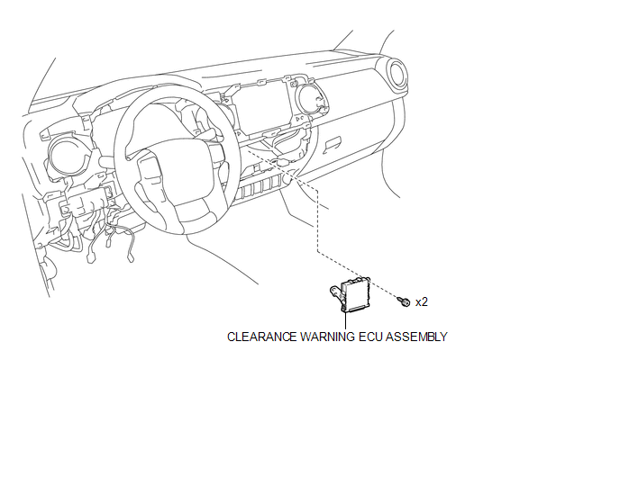
COMPONENTS
ILLUSTRATION
Installation
INSTALLATION
PROCEDURE
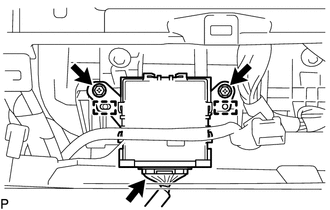
1. INSTALL CLEARANCE WARNING ECU ASSEMBLY
(a) Connect the connector.
(b) Engage the 2 guides to install the clearance warning ECU assembly.
(c) Install the 2 screws.
2. INSTALL AIR CONDITIONING CONTROL ASSEMBLY (for Automatic Air Conditioning System)
(See page .gif) )
)
3. INSTALL AIR CONDITIONING CONTROL ASSEMBLY (for Manual Air Conditioning System)
(See page )
Removal
REMOVAL
PROCEDURE
1. REMOVE AIR CONDITIONING CONTROL ASSEMBLY (for Automatic Air Conditioning System)
(See page .gif) )
)
2. REMOVE AIR CONDITIONING CONTROL ASSEMBLY (for Manual Air Conditioning System)
(See page )
3. REMOVE CLEARANCE WARNING ECU ASSEMBLY
|
(a) Remove the 2 screws. |
|
(b) Disengage the 2 guides to separate the clearance warning ECU assembly.
(c) Disconnect the connector to remove the clearance warning ECU assembly.
 Clearance Warning Buzzer
Components
COMPONENTS
ILLUSTRATION
Installation
INSTALLATION
PROCEDURE
1. INSTALL NO. 1 CLEARANCE WARNING BUZZER
(a) Connect the connector.
(b) Engage the clamp to install the No. 1 clea ...

Other materials:
Seat Belt Buckle Switch LH Circuit Malfunction (B1656/38)
DESCRIPTION
The seat belt buckle switch LH circuit consists of the airbag sensor assembly
and the front seat inner belt assembly LH (seat belt buckle switch LH).
DTC B1655/37 is stored when a malfunction is detected in the seat belt buckle
switch LH circuit.
DTC No.
DTC ...
Checking and replacing fuses
If any of the electrical components do not operate, a fuse may have blown.
If this happens, check and replace the fuses as necessary.
Turn the engine switch to the LOCK
position.
The fuses are located in the following
places. To check the fuses, follow the instructions below.
Engine comp ...
On-vehicle Inspection
ON-VEHICLE INSPECTION
PROCEDURE
1. INSPECT SIDE AIRBAG SENSOR ASSEMBLY (for Vehicle not Involved in Collision)
(a) Perform a Diagnostic System Check (See page
).
2. INSPECT SIDE AIRBAG SENSOR ASSEMBLY (for Vehicle Involved in Collision and
Airbag has not Deployed)
CAUTION:
For side airbag ...
