Toyota Tacoma (2015-2018) Service Manual: Differential Oil
Adjustment
ADJUSTMENT
PROCEDURE
1. INSPECT DIFFERENTIAL OIL
(a) Stop the vehicle on a level place.
(b) Remove the differential filler plug and gasket.
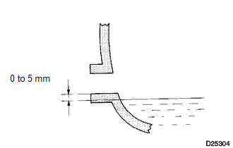
(c) Check that the oil level is within 5 mm (0 to 0.20 in.) of the bottom of the filler plug opening.
NOTICE:
- Excessively large or small quantities of oil may cause problems.
- After replacing the oil, drive the vehicle and check the oil level again.
HINT:
If necessary, fill the differential carrier assembly with differential gear oil.
Oil type and viscosity:
Toyota Genuine Differential gear oil LT SAE 75W-85 APL GL-5 or equivalent.
Capacity:
Front differential carrier assembly:
1.45 to 1.55 liters
(1.54 to 1.64 US qts, 1.28 to 1.36 Imp. qts)
Rear differential carrier assembly (for BD20D (EX Long Wheelbase )):
2.85 to 2.95 liters
(3.01 to 3.12 US qts, 2.51 to 2.60 Imp. qts)
Rear differential carrier assembly (for BD20D (SP Long Wheelbase)):
3.00 to 3.10 liters
(3.17 to 3.28 US qts, 2.64 to 2.73 Imp. qts)
Rear differential carrier assembly (for BD22A (EX Long Wheelbase)):
3.75 to 3.85 liters
(3.96 to 4.07 US qts, 3.30 to 3.39 Imp. qts)
Rear differential carrier assembly (for BD22AN (EX Long Wheelbase)):
3.75 to 3.85 liters
(3.96 to 4.07 US qts, 3.30 to 3.39 Imp. qts)
Rear differential carrier assembly (for BD22AN (SP Long Wheelbase)):
3.95 to 4.05 liters
(4.17 to 4.28 US qts, 3.48 to 3.56 Imp. qts)
(d) Check for oil leakage if the oil level is low.
(e) Install the differential filler plug and a new gasket.
Torque:
Front differential carrier assembly :
39 N·m {398 kgf·cm, 29 ft·lbf}
Rear differential carrier assembly :
49 N·m {500 kgf·cm, 36 ft·lbf}
 Installation
INSTALLATION
PROCEDURE
1. INSTALL REAR DIFFERENTIAL DRIVE PINION BEARING SPACER
(a) Install a new front differential drive pinion bearing spacer.
HINT:
Make sure the front differential drive pini ...

Other materials:
Transmitter ID not Registered (C2171/71)
DESCRIPTION
The IDs of each tire pressure warning valve and transmitter are registered to
the tire pressure warning ECU and receiver.
When the ECU detects that a transmitter ID code is not registered in the ECU,
this DTC is stored.
DTC No.
Detection Item
DTC D ...
Diagnosis System
DIAGNOSIS SYSTEM
1. DESCRIPTION
(a) Smart key system (for start function) data and the Diagnostic Trouble Codes
(DTCs) can be read through the Data Link Connector 3 (DLC3) of the vehicle. When
the system seems to be malfunctioning, use the Techstream to check for malfunctions
and perform rep ...
Components
COMPONENTS
ILLUSTRATION
ILLUSTRATION
ILLUSTRATION
ILLUSTRATION
ILLUSTRATION
ILLUSTRATION
ILLUSTRATION
ILLUSTRATION
...
