Toyota Tacoma (2015-2018) Service Manual: Installation
INSTALLATION
CAUTION / NOTICE / HINT
HINT:
The following procedures are for BD20 (w/o Differential Lock).
PROCEDURE
1. INSTALL REAR DIFFERENTIAL CARRIER ASSEMBLY
(a) Clean the contact surfaces of the rear differential carrier assembly and axle housing.
|
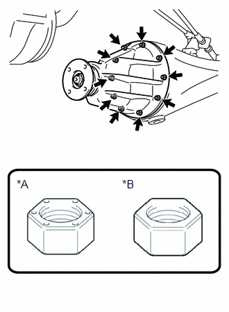
(b) Install the rear differential carrier assembly, a new rear differential carrier gasket and the washers with the 10 nuts. Text in Illustration
Torque: for Type A : 25 N·m {255 kgf·cm, 18 ft·lbf} for Type B : 37 N·m {377 kgf·cm, 27 ft·lbf} CAUTION: The rear differential carrier assembly is a heavy component. Make sure that it is supported securely. NOTICE:
|
|
2. INSTALL REAR AXLE SHAFT WITH BACKING PLATE LH
(See page .gif) )
)
3. INSTALL REAR AXLE SHAFT WITH BACKING PLATE RH
HINT:
Use the same procedure described for the LH side.
4. BLEED AIR FROM BRAKE LINE (for Hydraulic Brake Booster)
(See page )
5. BLEED AIR FROM BRAKE LINE (for Vacuum Brake Booster)
(See page )
6. ADD DIFFERENTIAL OIL
(See page )
7. INSTALL REAR PROPELLER SHAFT ASSEMBLY (for 2WD)
(See page )
8. INSTALL REAR PROPELLER SHAFT ASSEMBLY (for 4WD)
(See page )
9. ADJUST PARKING BRAKE
(See page )
10. INSTALL REAR WHEELS
Torque:
113 N·m {1152 kgf·cm, 83 ft·lbf}
11. CHECK ABS SPEED SENSOR SIGNAL (for Hydraulic Brake Booster)
(See page )
12. CHECK ABS SPEED SENSOR SIGNAL (for Vacuum Brake Booster)
(See page )
 Removal
REMOVAL
CAUTION / NOTICE / HINT
Text in Illustration
*a
Object Exceeding Weight Limit of Transmission Jack
Be sure to perform this procedure with several peo ...

Other materials:
Terminals Of Ecm
TERMINALS OF ECM
1. ECM
HINT:
The standard voltage between each pair of ECM terminals is shown in the table
below. In the table, first follow the information under "Condition". Look under
"Terminal No. (Symbol)" for the terminals to be inspected. The standard voltage
b ...
Cruise Control System Internal Failure (P057504,P057549)
DESCRIPTION
This DTC is stored when there is a malfunction in the ECM.
DTC No.
Detection Item
DTC Detection Condition
Trouble Area
MIL
P057504
Cruise Control System Internal Failure
While the dynamic rada ...
Washer Level Warning Switch
Components
COMPONENTS
ILLUSTRATION
Inspection
INSPECTION
PROCEDURE
1. INSPECT LEVEL WARNING SWITCH ASSEMBLY
HINT:
This check should be performed with the windshield washer motor and pump assembly
installed on the washer jar.
(a) Fill the washer jar with washer fluid.
(b) ...
