Toyota Tacoma (2015-2018) Service Manual: Air Inlet Damper Position Sensor Circuit (B1432/32)
DESCRIPTION
This sensor detects the position of the air inlet damper and sends the appropriate signals to the air conditioning amplifier assembly. The position sensor is built into the No. 1 air conditioning servo assembly (fresh/recirculation damper).
|
DTC No. |
DTC Detection Condition |
Trouble Area |
|---|---|---|
|
B1432/32 |
Short to ground or power source circuit air inlet damper position sensor circuit. |
|
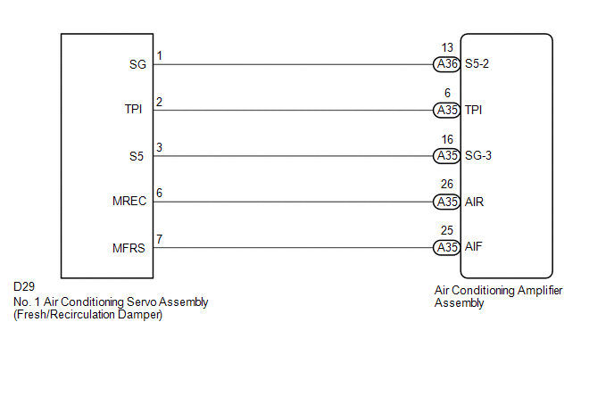
WIRING DIAGRAM
PROCEDURE
|
1. |
READ VALUE USING TECHSTREAM |
(a) Connect the Techstream to the DLC3.
(b) Turn the ignition switch to ON.
(c) Turn the Techstream on.
(d) Operate the recirculation/fresh switch.
(e) Enter the following menus: Body Electrical / Air Conditioner / Data List.
(f) Check the value(s) by referring to the table below.
Air Conditioner|
Tester Display |
Measurement Item/Range |
Normal Condition |
Diagnostic Note |
|---|---|---|---|
|
Air Inlet Damper Position |
Air inlet damper servo motor actual position / Air inlet damper servo motor actual position / Min.: -14.0% Max.: 113.5% |
FRESH: 0.0% RECIRCULATION: 100.0% |
- |
|
Air Inlet Damper Target |
Air inlet damper servo motor target position / Min.: -14.0% Max.: 113.5% |
FRESH: 0.0% RECIRCULATION: 100.0% |
- |
OK:
The display is as specified in the Normal Condition column.
|
Result |
Proceed to |
|---|---|
|
NG |
A |
|
OK (When troubleshooting according to Problem Symptoms Table) |
B |
|
OK (When troubleshooting according to the DTC) |
C |
| B | .gif) |
PROCEED TO NEXT SUSPECTED AREA SHOWN IN PROBLEM SYMPTOMS TABLE |
| C | |
REPLACE AIR CONDITIONING AMPLIFIER ASSEMBLY |
|
.gif)
|
2. |
INSPECT NO. 1 AIR CONDITIONING SERVO ASSEMBLY (FRESH/RECIRCULATION DAMPER) |
(a) Remove the No. 1 air conditioning servo assembly (fresh/recirculation damper)
(See page .gif) ).
).
(b) Inspect the No. 1 air conditioning servo assembly (fresh/recirculation damper)
(See page ).
| NG | |
REPLACE NO. 1 AIR CONDITIONING SERVO ASSEMBLY (FRESH/RECIRCULATION DAMPER) |
|
|
3. |
CHECK HARNESS AND CONNECTOR (NO. 1 AIR CONDITIONING SERVO ASSEMBLY - AIR CONDITIONING AMPLIFIER ASSEMBLY) |
(a) Disconnect the D29 No. 1 air conditioning servo assembly (fresh/recirculation damper) connector.
(b) Disconnect the A35 and A36 air conditioning amplifier assembly connectors.
(c) Measure the resistance according to the value(s) in the table below.
Standard Resistance:
|
Tester Connection |
Condition |
Specified Condition |
|---|---|---|
|
D29-1 (SG) - A36-13 (S5-2) |
Always |
Below 1 Ω |
|
D29-2 (TPI) - A35-6 (TPI) |
Always |
Below 1 Ω |
|
D29-3 (S5) - A35-16 (SG-3) |
Always |
Below 1 Ω |
|
D29-1 (SG) or A36-13 (S5-2) - Body ground |
Always |
10 kΩ or higher |
|
D29-2 (TPI) or A35-6 (TPI) - Body ground |
Always |
10 kΩ or higher |
|
D29-3 (S5) or A35-16 (SG-3) - Body ground |
Always |
10 kΩ or higher |
| OK | |
REPLACE AIR CONDITIONING AMPLIFIER ASSEMBLY |
| NG | |
REPAIR OR REPLACE HARNESS OR CONNECTOR |
 Air Mix Damper Position Sensor Circuit (Passenger Side) (B1431/31)
DESCRIPTION
This sensor detects the position of the air mix damper (for front passenger side)
and sends the appropriate signals to the air conditioning amplifier assembly. The
position sensor is ...
 Lost Communication with ECM (U0100,U0142,U0155)
DESCRIPTION
DTC No.
DTC Detecting Condition
Trouble Area
U0100
No communication with ECM
CAN communication system
...
Other materials:
Internal Control Module EEPROM Data Memory Failure (P062F44)
DESCRIPTION
The ECM monitors its internal operation and it will set this DTC when it detects
an internal malfunction.
DTC No.
DTC Detection Condition
Trouble Area
SAE
P062F44
ECM internal error (EEPROM)
ECM
...
Disposal
DISPOSAL
CAUTION / NOTICE / HINT
HINT:
The tire pressure warning valve and transmitter is powered by a lithium battery.
When disposing of the tire pressure warning valve and transmitter, remove the battery
and dispose of it correctly.
PROCEDURE
1. DISPOSE OF TIRE PRESSURE WARNING VALVE AND ...
4WD ECU Malfunction (P163B)
DESCRIPTION
This DTC is output when a malfunction is detected in the 4 wheel drive control
ECU internal circuit.
DTC No.
Detection Item
DTC Detection Condition
Trouble Area
P163B
4WD ECU Malfunction
Dia ...
