Toyota Tacoma (2015-2018) Service Manual: Removal
REMOVAL
CAUTION / NOTICE / HINT
 Text in Illustration
|
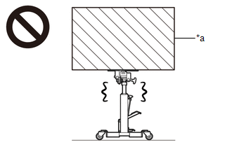
*a |
Object Exceeding Weight Limit of Transmission Jack |
- Be sure to perform this procedure with several people as the rear differential carrier assembly is very heavy.
- Be sure to follow the procedure described in the repair manual, or the transmission jack may suddenly drop or a part may fall.
HINT:
The following procedures are for BD20 (w/o Differential Lock).
PROCEDURE
1. REMOVE REAR WHEELS
2. REMOVE REAR PROPELLER SHAFT ASSEMBLY (for 2WD)
(See page .gif) )
)
3. REMOVE REAR PROPELLER SHAFT ASSEMBLY (for 4WD)
(See page )
4. DRAIN DIFFERENTIAL OIL
(See page )
5. REMOVE REAR AXLE SHAFT WITH BACKING PLATE LH
(See page )
6. REMOVE REAR AXLE SHAFT WITH BACKING PLATE RH
HINT:
Use the same procedure described for the LH side.
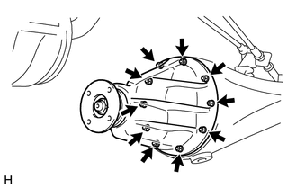
7. REMOVE REAR DIFFERENTIAL CARRIER ASSEMBLY
|
(a) Remove the 10 nuts, 10 washers and rear differential carrier assembly. CAUTION: The rear differential carrier assembly is a heavy component. Make sure that it is supported securely. NOTICE:
|
|
8. REMOVE REAR DIFFERENTIAL CARRIER GASKET
 Components
COMPONENTS
ILLUSTRATION
HINT:
The following specifications are for BD20D (w/o Differential Lock). BD20D differentials
are equipped with M8 rear differential carrier to rear axel housing fasteners ...
 Installation
INSTALLATION
CAUTION / NOTICE / HINT
HINT:
The following procedures are for BD20 (w/o Differential Lock).
PROCEDURE
1. INSTALL REAR DIFFERENTIAL CARRIER ASSEMBLY
(a) Clean the contact surfaces o ...
Other materials:
On-vehicle Inspection
ON-VEHICLE INSPECTION
PROCEDURE
1. INSPECT REFRIGERANT PRESSURE WITH MANIFOLD GAUGE SET
(a) This is a method to specify trouble areas by using a manifold gauge set.
Read the manifold gauge pressure when the following conditions are established.
Test conditions:
Engine has been warmed u ...
Seatback table
Front passenger’s seatback can be used as a temporary table only when the
vehicle is stopped.
Fold down the front passenger’s seat to use the seatback table.
CAUTION
■Caution while driving
Observe the following precautions to avoid death or serious injury.
●Do not set up the ...
Installation
INSTALLATION
PROCEDURE
1. INSTALL WINDSHIELD WIPER SWITCH ASSEMBLY
(a) Engage the claw to install the windshield wiper switch assembly.
(b) Connect the 2 connectors.
2. INSTALL UPPER STEERING COLUMN COVER
3. INSTALL LOWER STEERING COLUMN COVER
...
