Toyota Tacoma (2015-2018) Service Manual: Components
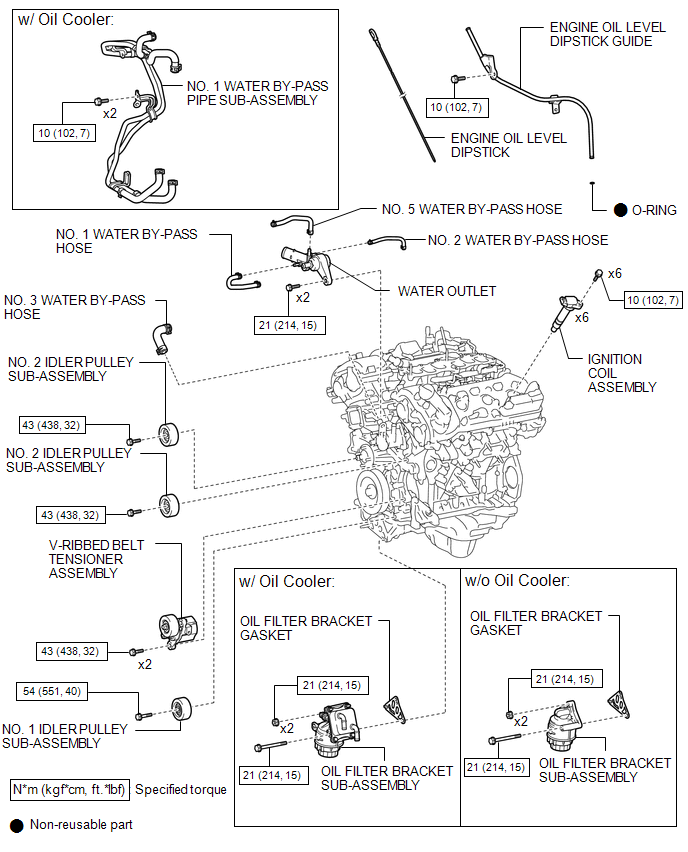
COMPONENTS
ILLUSTRATION
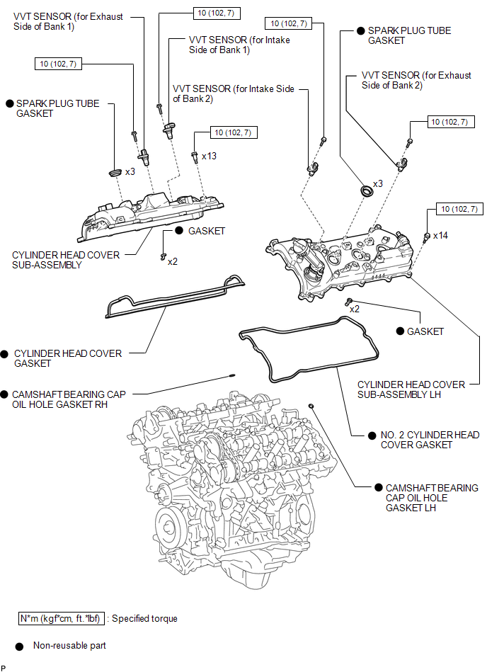
ILLUSTRATION
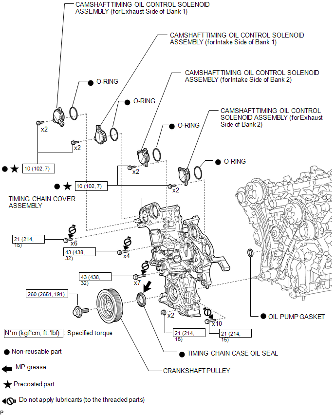
ILLUSTRATION
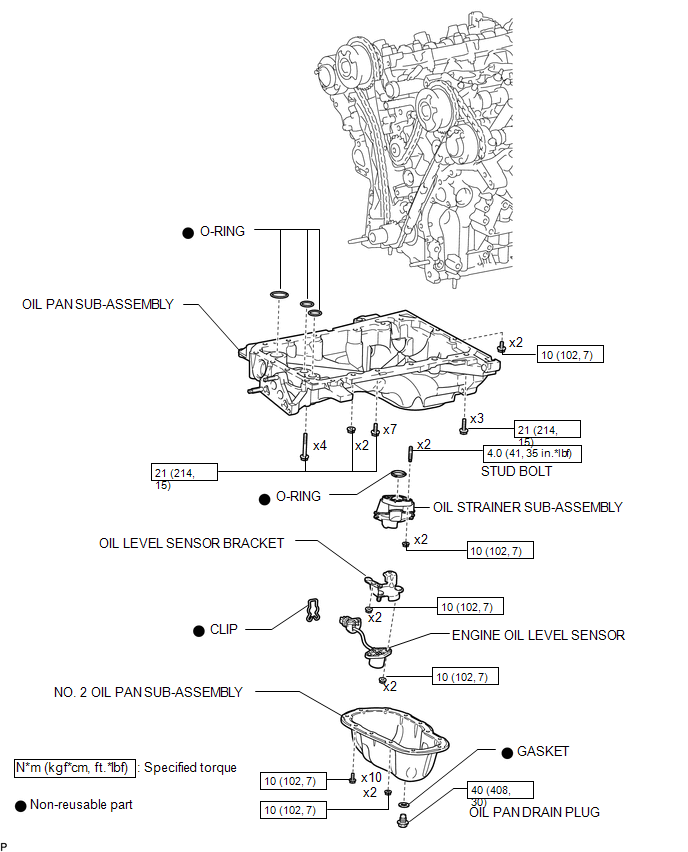
ILLUSTRATION
ILLUSTRATION
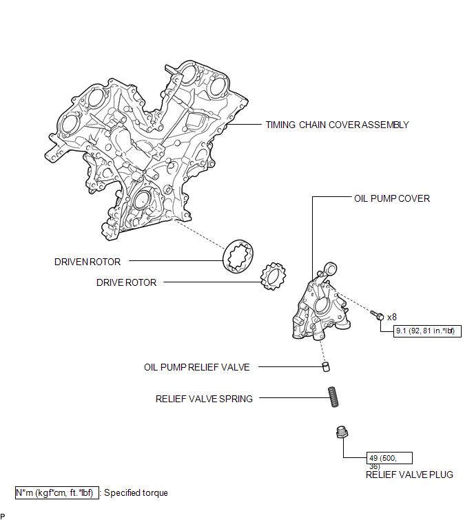
 Oil Pump
...
 Disassembly
DISASSEMBLY
PROCEDURE
1. REMOVE OIL PUMP RELIEF VALVE
(a) Using a 27 mm socket wrench, remove the oil pump relief valve plug.
(b) Remove the oil pump relief valve spring and oil pump re ...
Other materials:
Front Speed Sensor RH Malfunction (C1401,C1402)
DESCRIPTION
The speed sensor detects wheel speed and sends the appropriate signals to the
skid control ECU (brake actuator assembly). These signals are used for brake control.
The speed sensor rotors have rows of alternating N and S magnetic poles and their
magnetic fields change when the roto ...
Brake Switch "B" Circuit Short to Battery (P070312)
DESCRIPTION
The purpose of this circuit is to prevent the engine from stalling while driving
in lock-up when the brakes are suddenly applied.
When the brake pedal is depressed, this switch sends a signal to the ECM. Then
the ECM cancels the operation of the lock-up clutch while braking is in p ...
Operation Check
OPERATION CHECK
1. NOTICE WHEN CHECKING FOLLOWING
(a) Wireless door lock/unlock function:
This wireless door lock control function operates only when the following 3 conditions
are met:
(1) The engine switch is off.
(2) All doors are closed.
(3) The power door lock control system is operatin ...
