Toyota Tacoma (2015-2018) Service Manual: Installation
INSTALLATION
PROCEDURE
1. INSTALL FRONT AXLE HUB
2. INSTALL FRONT SUSPENSION UPPER ARM

(a) Install a new nut and clip.
Torque:
110 N·m {1122 kgf·cm, 81 ft·lbf}
3. INSTALL FRONT SUSPENSION LOWER ARM
.png)
(a) Install the front suspension lower arm with the 2 bolts.
Torque:
160 N·m {1631 kgf·cm, 118 ft·lbf}
4. INSTALL TIE ROD END SUB-ASSEMBLY
(a) Install the tie rod end with the nut.
Torque:
91 N·m {928 kgf·cm, 67 ft·lbf}
(b) Install a new cotter pin.
NOTICE:
If the holes in the cotter pin are not aligned, tighten the nut an additional 60°.
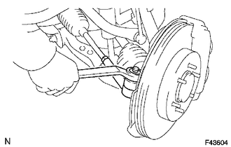
5. INSTALL FRONT STABILIZER LINK ASSEMBLY
.png)
(a) Install the stabilizer link onto the steering knuckle with the nut.
Torque:
70 N·m {714 kgf·cm, 52 ft·lbf}
HINT:
If the ball joint turns together with the nut, use a hexagon (6 mm) wrench to hold the stud.
6. INSTALL FRONT AXLE HUB NUT (for 4WD)
.png)
(a) Install the hub nut.
Torque:
235 N·m {2396 kgf·cm, 173 ft·lbf}
(b) Install the adjusting cap and cotter pin.
7. INSTALL FRONT AXLE HUB GREASE CAP (for 4WD)
8. INSTALL FRONT DISC
9. INSTALL FRONT DISC BRAKE CALIPER ASSEMBLY
.png)
(a) Install the front disc brake caliper with the 2 bolts.
Torque:
123 N·m {1254 kgf·cm, 91 ft·lbf}
|
(b) Install the brake tube bracket onto the steering knuckle with the bolt. Torque: 29 N·m {296 kgf·cm, 21 ft·lbf} |
|
.png)
|
(c) Using a union nut wrench, connect the brake tube to the disc brake cylinder. Torque: 15 N·m {155 kgf·cm, 11 ft·lbf} |
|
.png)
10. INSTALL FRONT SPEED SENSOR
|
(a) Install the speed sensor wire harness onto the steering knuckle with the bolt. Torque: 13 N·m {133 kgf·cm, 10 ft·lbf} |
|
.png)
(b) Engage the 2 clips.
(c) Install the speed sensor with the bolt.
Torque:
8.3 N·m {85 kgf·cm, 73 in·lbf}
11. INSTALL FRONT WHEEL
Torque:
113 N·m {1152 kgf·cm, 83 ft·lbf}
12. CONNECT CABLE TO NEGATIVE BATTERY TERMINAL
Torque:
5.4 N·m {55 kgf·cm, 48 in·lbf}
NOTICE:
When disconnecting the cable, some systems need to be initialized after the cable is reconnected.
Click here .gif)
13. FILL RESERVOIR WITH BRAKE FLUID (for Hydraulic Brake Booster)
Click here
14. FILL RESERVOIR WITH BRAKE FLUID (for Vacuum Brake Booster)
Click here
15. BLEED MASTER CYLINDER (for Vacuum Brake Booster)
Click here
16. BLEED BRAKE LINE (for Hydraulic Brake Booster)
Click here
17. BLEED BRAKE LINE (for Vacuum Brake Booster)
Click here
18. INSPECT FLUID LEVEL IN RESERVOIR (for Hydraulic Brake Booster)
Click here
19. INSPECT FLUID LEVEL IN RESERVOIR (for Vacuum Brake Booster)
Click here
20. INSPECT FOR BRAKE FLUID LEAK
21. CHECK VSC SENSOR SIGNAL (for Hydraulic Brake Booster)
Click here
22. CHECK VSC SENSOR SIGNAL (for Vacuum Brake Booster)
Click here
23. INSPECT AND ADJUST FRONT WHEEL ALIGNMENT
Click here
 Removal
REMOVAL
PROCEDURE
1. PRECAUTION
NOTICE:
After turning the ignition switch off, waiting time may be required before disconnecting
the cable from the negative (-) battery terminal.
Therefore, mak ...
 Front Axle Hub Bolt
Installation
INSTALLATION
PROCEDURE
1. INSTALL FRONT AXLE HUB BOLT
(a) Install a new hub bolt through the axle hub.
(b) Install the washer plate, as shown in the illustration, through the hub ...
Other materials:
Data List / Active Test
DATA LIST / ACTIVE TEST
NOTICE:
In the table below, the values listed under "Normal Condition" are reference
values. Do not depend solely on these reference values when deciding whether a part
is faulty or not.
HINT:
Using the Techstream to read the Data List allows the values or s ...
Diagnosis System
DIAGNOSIS SYSTEM
1. DESCRIPTION
The 4 wheel drive control ECU records DTCs when the ECU detects a malfunction
in the ECU itself or in system circuits.
The DTCs can be read through the DLC3 of the vehicle. When the system seems to
be malfunctioning, use the Techstream to check for malfunctions ...
Installation
INSTALLATION
PROCEDURE
1. INSTALL CLUTCH PEDAL NO.1 CUSHION
(a) Install the clutch pedal No. 1 cushion to the clutch pedal sub-assembly.
2. INSTALL CLUTCH PEDAL SHAFT COLLAR
(a) Apply MP grease to the clutch pedal shaft collar.
Text in Illustration
MP grease
(b) ...
