Toyota Tacoma (2015-2018) Service Manual: Removal
REMOVAL
PROCEDURE
1. REMOVE PROPELLER SHAFT WITH CENTER BEARING ASSEMBLY
|
(a) Place matchmarks on the propeller shaft flange yoke and differential flange. Text in Illustration
|
|
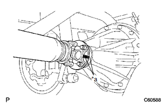
(b) for Differential Type BD20:
(1) Remove the 4 nuts, 4 bolts and 4 washers to disconnect the propeller shaft.
(c) for Differential Type BD22:
(1) Remove the 4 nuts and 4 washers to disconnect the propeller shaft.
|
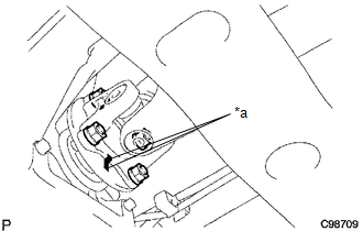
(d) Remove the 2 bolts to separate the center No. 2 support bearing assembly from the frame crossmember. |
|
.png)
|
(e) Place matchmarks on the propeller shaft flange yoke and transfer flange. Text in Illustration
|
|
(f) Remove the 4 nuts, 4 washers and propeller shaft.
 Components
COMPONENTS
ILLUSTRATION
...
 Disassembly
DISASSEMBLY
PROCEDURE
1. REMOVE REAR PROPELLER SHAFT BOOT CLAMP
(a) Place matchmarks on the propeller shaft and sleeve yoke.
Text in Illustration
*1
...
Other materials:
Navigation Receiver
Components
COMPONENTS
ILLUSTRATION
ILLUSTRATION
Removal
REMOVAL
PROCEDURE
1. REMOVE INSTRUMENT CLUSTER CENTER FINISH PANEL SUB-ASSEMBLY
(See page )
2. REMOVE NAVIGATION RECEIVER ASSEMBLY WITH BRACKET
(a) Remove the 4 bolts.
(b ...
Check Bus 3 Line for Short to +B
DESCRIPTION
There may be a short circuit between one of the CAN bus lines and +B when no
resistance exists between terminal 6 (CA3H) of the central gateway ECU (network
gateway ECU) and terminal 16 (BAT) of the DLC3, or terminal 21 (CA3L) of the central
gateway ECU (network gateway ECU) and t ...
Installation
INSTALLATION
CAUTION / NOTICE / HINT
CAUTION:
Wear protective gloves. Sharp areas on the parts may injure your hands.
HINT:
Use the same procedure for both the RH and LH sides.
The procedure described below is for the LH side.
PROCEDURE
1. INSTALL FRONT SEAT AIRBAG ASSEMBLY ...
