Toyota Tacoma (2015-2018) Service Manual: Components
COMPONENTS
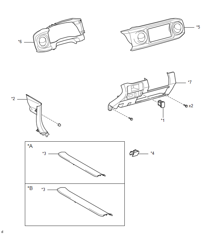
ILLUSTRATION
|
*A |
for Double Cab |
*B |
for Access Cab |
|
*1 |
AUTO HIGH BEAM SWITCH |
*2 |
COWL SIDE TRIM BOARD LH |
|
*3 |
FRONT DOOR SCUFF PLATE LH |
*4 |
HOOD LOCK CONTROL LEVER SUB-ASSEMBLY |
|
*5 |
INSTRUMENT CLUSTER CENTER FINISH PANEL SUB-ASSEMBLY |
*6 |
INSTRUMENT CLUSTER FINISH PANEL ASSEMBLY |
|
*7 |
INSTRUMENT PANEL LOWER FINISH PANEL SUB-ASSEMBLY |
- |
- |

 Inspection
INSPECTION
PROCEDURE
1. INSPECT AUTO HIGH BEAM SWITCH
*a
Component without harness connected
(Auto High Beam Switch)
(a) Check the resistance.
(1) Measure the ...
Other materials:
Front Radar Sensor Incorrect Axial Gap (C1A11,C1A14)
DESCRIPTION
When the system determines that the vehicle is driving straight ahead based on
signals from the yaw rate and acceleration sensor (airbag sensor assembly), etc.,
the millimeter wave radar sensor assembly performs self-diagnosis to check if the
sensor beam axis is misaligned.
C1A11 ...
Steering Pad Switch
Components
COMPONENTS
ILLUSTRATION
*1
STEERING PAD SWITCH ASSEMBLY
-
-
Removal
REMOVAL
PROCEDURE
1. REMOVE STEERING PAD
(See page )
2. REMOVE STEERING PAD SWITCH ASSEMBLY
(a) Disconnect the 2 connectors.
...
If the vehicle battery is discharged
The following procedures may be used to start the engine if the vehicle’s
battery is discharged.
You can call your Toyota dealer or qualified repair shop.
If you have a set of jumper (or booster) cables and a second vehicle with a 12-volt
battery, you can jump start your Toyota following the ...
