Toyota Tacoma (2015-2018) Service Manual: Crawl Switch
Components
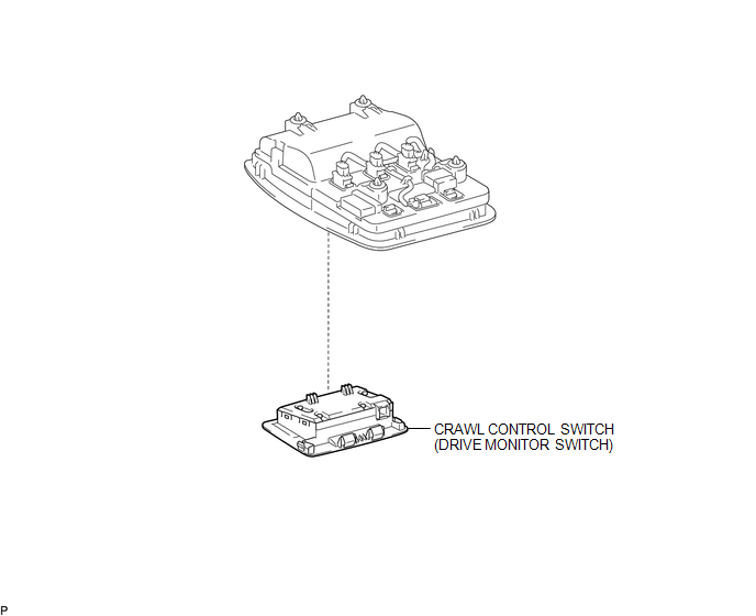
COMPONENTS
ILLUSTRATION
Inspection
INSPECTION
PROCEDURE
1. INSPECT CRAWL CONTROL SWITCH (DRIVE MONITOR SWITCH)
(a) Check the resistance.
(1) Measure the resistance according to the value(s) in the table below.
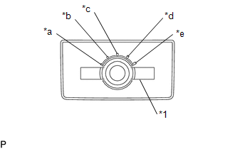 Text in Illustration
|
*1 |
Crawl Control Switch |
|
*a |
Low |
|
*b |
Between Low and Medium |
|
*c |
Medium |
|
*d |
Between Medium and High |
|
*e |
High |
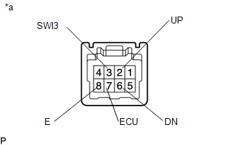
Standard Resistance:
|
Tester Connection |
Switch Condition |
Specified Condition |
|---|---|---|
|
7 (ECU) - 8 (E) |
Low |
Below 1 Ω |
|
2 (UP) - 8 (E) |
||
|
6 (DN) - 8 (E) |
10 kΩ or higher |
|
|
7 (ECU) - 8 (E) |
Between Low and Medium |
Below 1 Ω |
|
2 (UP) - 8 (E) |
||
|
6 (DN) - 8 (E) |
10 kΩ or higher |
|
|
7 (ECU) - 8 (E) |
Medium |
Below 1 Ω |
|
2 (UP) - 8 (E) |
||
|
6 (DN) - 8 (E) |
10 kΩ or higher |
|
|
7 (ECU) - 8 (E) |
Between Medium and High |
Below 1 Ω |
|
2 (UP) - 8 (E) |
||
|
6 (DN) - 8 (E) |
10 kΩ or higher |
|
|
7 (ECU) - 8 (E) |
High |
Below 1 Ω |
|
2 (UP) - 8 (E) |
||
|
6 (DN) - 8 (E) |
10 kΩ or higher |
|
|
3 (SWl3) - 8 (E) |
ON/OFF: Pressed |
Below 1 Ω |
|
ON/OFF: Not pressed |
10 kΩ or higher |
|
*a |
Component without harness connected (Crawl Control Switch (Drive Monitor Switch)) |
If the result is not as specified, replace the crawl control switch (drive monitor switch).
Removal
REMOVAL
PROCEDURE
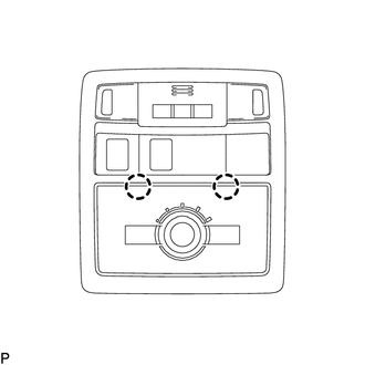
1. REMOVE CRAWL CONTROL SWITCH (DRIVE MONITOR SWITCH)
|
(a) Disengage the 2 claws to remove the crawl control switch (drive monitor switch). |
|
Installation
INSTALLATION
PROCEDURE
1. INSTALL CRAWL CONTROL SWITCH (DRIVE MONITOR SWITCH)
(a) Engage the 2 claws to install the crawl control switch (drive monitor switch).
 Removal
REMOVAL
PROCEDURE
1. PRECAUTION
NOTICE:
After turning the ignition switch off, waiting time may be required before disconnecting
the cable from the negative (-) battery terminal.
Therefore, mak ...
 Front Speed Sensor
Removal
REMOVAL
PROCEDURE
1. PRECAUTION
NOTICE:
After turning the ignition switch off, waiting time may be required before disconnecting
the cable from the negative (-) battery terminal.
The ...
Other materials:
Disposal
DISPOSAL
PROCEDURE
1. DISPOSE OF BRAKE BOOSTER ACCUMULATOR ASSEMBLY
(a) Place the brake booster accumulator in a vise and cover it with a cloth.
(b) Slowly cut a hole on the brake booster accumulator side in the A portion
shown in the illustration on the left. And discharge the gas and liqui ...
Transfer Shift Motor Limit Switch Circuit (P17AC)
DESCRIPTION
When the transfer switches modes, the TL1, TL2 and TL3 terminals of the limit
switch are in one of the ON/OFF combinations listed in the table below.
Terminal
When 2WD
Switching between 2WD and H4
When H4
Switching between H4 and ...
Power Outlet Socket(for Rear Side)
Components
COMPONENTS
ILLUSTRATION
*1
USB CHARGER SOCKET
-
-
Removal
REMOVAL
PROCEDURE
1. REMOVE REAR CONSOLE BOX ASSEMBLY
Click here
2. REMOVE USB CHARGER SOCKET
(a) Disengage the 4 claws to remove the USB charger soc ...
