Toyota Tacoma (2015-2018) Service Manual: System Diagram
SYSTEM DIAGRAM
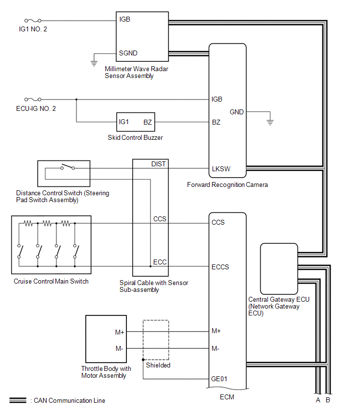
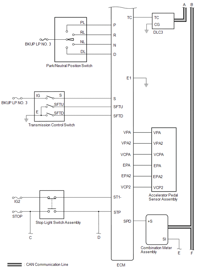
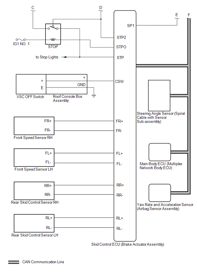 Communication Table
|
Sender |
Receiver |
Signal |
Line |
|---|---|---|---|
|
ECM |
Millimeter Wave Radar Sensor Assembly |
|
CAN |
|
ECM |
Skid Control ECU (Brake Actuator Assembly) |
|
CAN |
|
ECM |
Combination Meter Assembly |
|
CAN |
|
ECM |
Forward Recognition Camera |
Cruise control operation signal |
CAN |
|
Millimeter Wave Radar Sensor Assembly |
ECM |
|
CAN |
|
Millimeter Wave Radar Sensor Assembly |
Combination Meter Assembly |
Millimeter wave radar sensor beam axis deviation signal |
CAN |
|
Skid Control ECU (Brake Actuator Assembly) |
Millimeter Wave Radar Sensor Assembly |
|
CAN |
|
Skid Control ECU (Brake Actuator Assembly) |
ECM |
|
CAN |
|
Steering Angle Sensor (Spiral Cable with Sensor Sub-assembly) |
Millimeter Wave Radar Sensor Assembly |
|
CAN |
|
Main Body ECU (Multiplex Network Body ECU) |
Millimeter Wave Radar Sensor Assembly |
Destination information signal |
CAN |
|
Yaw Rate and Acceleration Sensor (Airbag Sensor Assembly) |
Millimeter Wave Radar Sensor Assembly |
|
CAN |
 Precaution
PRECAUTION
IGNITION SWITCH EXPRESSIONS
(a) The type of ignition switch used on this model differs according to the specifications
of the vehicle. The expressions listed in the table below are used ...
 How To Proceed With Troubleshooting
CAUTION / NOTICE / HINT
HINT:
Perform the following procedure to troubleshoot the dynamic radar cruise
control system.
*: Use the Techstream.
PROCEDURE
1.
...
Other materials:
How To Proceed With Troubleshooting
CAUTION / NOTICE / HINT
HINT:
Use the following procedure to troubleshoot the sliding roof system.
*: Use the Techstream.
PROCEDURE
1.
VEHICLE BROUGHT TO WORKSHOP
NEXT
...
Installation
INSTALLATION
PROCEDURE
1. INSTALL ROOF HEADLINING ASSEMBLY
(a) Insert the roof headlining assembly into the vehicle from the front
door RH side.
NOTICE:
Check that the corners of the roof headlining assembly are not
folded, twisted or otherwise deformed and ...
Driving assist systems
To help enhance driving safety and performance, the following systems operate
automatically in response to various driving situations.
Be aware, however, that these systems are supplementary and should not be relied
upon too heavily when operating the vehicle.
■ ABS (Anti-lock Brake Syst ...
