Toyota Tacoma (2015-2018) Service Manual: Parking Brake Cable
Components
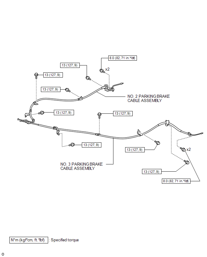
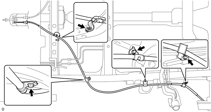
COMPONENTS
ILLUSTRATION
Removal
REMOVAL
PROCEDURE
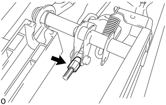
1. DISCONNECT NO. 2 PARKING BRAKE SHOE ASSEMBLY WITH PARKING BRAKE SHOE LEVER
(See page .gif) )
)
2. REMOVE VOLTAGE INVERTER ASSEMBLY
(See page )
3. REMOVE NO. 2 PARKING BRAKE CABLE ASSEMBLY
|
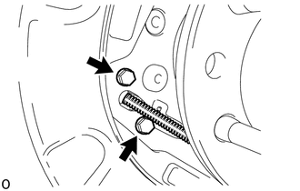
(a) Loosen the adjusting nut. |
|
|
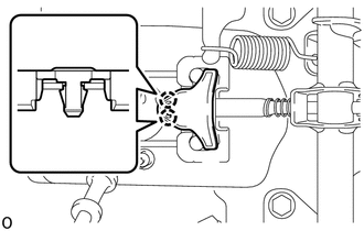
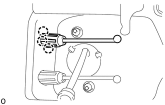
(b) Disengage the 2 claws to remove the parking cable end stopper. |
|
(c) Disconnect the No. 2 parking brake cable assembly from the No. 1 parking brake pull rod.
|
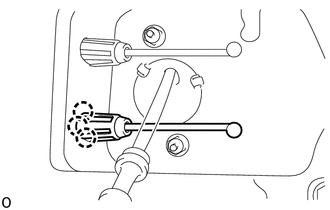
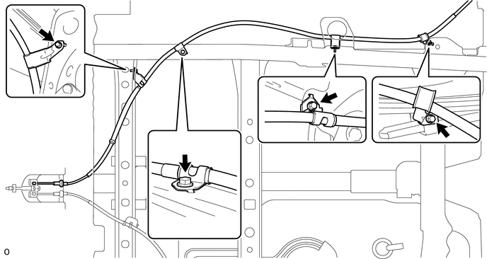
(d) Disengage the 3 claws of the No. 2 parking brake cable assembly and push the No. 2 parking brake cable assembly outside of vehicle slightly. |
|
|
(e) Remove the 2 bolts and disconnect the No. 2 parking brake cable assembly from the backing plate. |
|
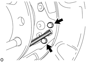
(f) Remove the 4 bolts and No. 2 parking brake cable assembly.
4. REMOVE NO. 3 PARKING BRAKE CABLE ASSEMBLY
|
(a) Loosen the adjusting nut. |
|
|
(b) Disengage the 2 claws to remove the parking cable end stopper. |
|
(c) Disconnect the No. 3 parking brake cable assembly from the No. 1 parking brake pull rod.
|
(d) Disengage the 3 claws of the No. 3 parking brake cable assembly and push the No. 3 parking brake cable assembly outside of vehicle slightly. |
|
|
(e) Remove the 2 bolts and disconnect the No. 3 parking brake cable assembly from the backing plate. |
|
(f) Remove the 4 bolts and No. 3 parking brake cable assembly.
Installation
INSTALLATION
PROCEDURE
1. INSTALL NO. 3 PARKING BRAKE CABLE ASSEMBLY
(a) Install the No. 3 parking cable assembly with the 4 bolts.
Torque:
13 N·m {127 kgf·cm, 9 ft·lbf}
(b) Attach the claws of the No. 3 parking brake cable assembly.
(c) Connect the No. 3 parking brake cable assembly to the No. 1 parking brake pull rod.
(d) Engage the 2 claws to install the parking brake cable end stopper.
(e) Install the No. 3 parking brake cable assembly to the backing plate with the 2 bolts.
Torque:
8.0 N·m {82 kgf·cm, 71 in·lbf}
2. INSTALL NO. 2 PARKING BRAKE CABLE ASSEMBLY
(a) Install the No. 2 parking brake cable assembly with the 4 bolts.
Torque:
13 N·m {127 kgf·cm, 9 ft·lbf}
(b) Attach the claws of the No. 2 parking brake cable assembly.
(c) Connect the No. 2 parking brake cable assembly to the No. 1 parking brake pull rod.
(d) Engage the 2 claws to install the parking brake cable end stopper.
(e) Install the No. 2 parking brake cable assembly to the backing plate with the 2 bolts.
Torque:
8.0 N·m {82 kgf·cm, 71 in·lbf}
3. CONNECT NO. 2 PARKING BRAKE SHOE ASSEMBLY WITH PARKING BRAKE SHOE LEVER
(See page .gif) )
)
4. INSPECT PARKING BRAKE LEVER TRAVEL
5. ADJUST PARKING BRAKE LEVER TRAVEL
6. INSTALL VOLTAGE INVERTER ASSEMBLY
(See page )
7. INSTALL REAR WHEEL
Torque:
113 N·m {1152 kgf·cm, 83 ft·lbf}
 Parking Brake
...
 Parking Brake Lever
Components
COMPONENTS
ILLUSTRATION
ILLUSTRATION
Installation
INSTALLATION
PROCEDURE
1. INSTALL PARKING BRAKE SWITCH ASSEMBLY
2. INSTALL PARKING BRAKE LEVER SUB-ASSEMBLY
(a) Install ...
Other materials:
System Diagram
SYSTEM DIAGRAM
Communication Table
Transmitting ECU
Receiving ECU
Signal
Communication Method
Power Window Regulator Master Switch Assembly
Power Window Regulator Motor Assembly (for Driver Door)
Power Window ...
Terminals Of Ecu
TERMINALS OF ECU
1. CHECK MAIN BODY ECU (MULTIPLEX NETWORK BODY ECU) AND DRIVER SIDE JUNCTION
BLOCK
(a) Disconnect the main body ECU (multiplex network body ECU) connectors.
Text in Illustration
*1
Main Body ECU (Multiplex Network Body ECU)
-
-
...
Vehicle load limits
Vehicle load limits include total load capacity, seating capacity, TWR (Trailer
Weight Rating) and cargo capacity.
■ Total load capacity (vehicle capacity weight):
Total load capacity means the combined weight of occupants, cargo and luggage.
■ Seating capacity:
Regular Cab models ...
