Toyota Tacoma (2015-2018) Service Manual: Multi-terrain Select Switch
Components
COMPONENTS
ILLUSTRATION
Removal
REMOVAL
PROCEDURE
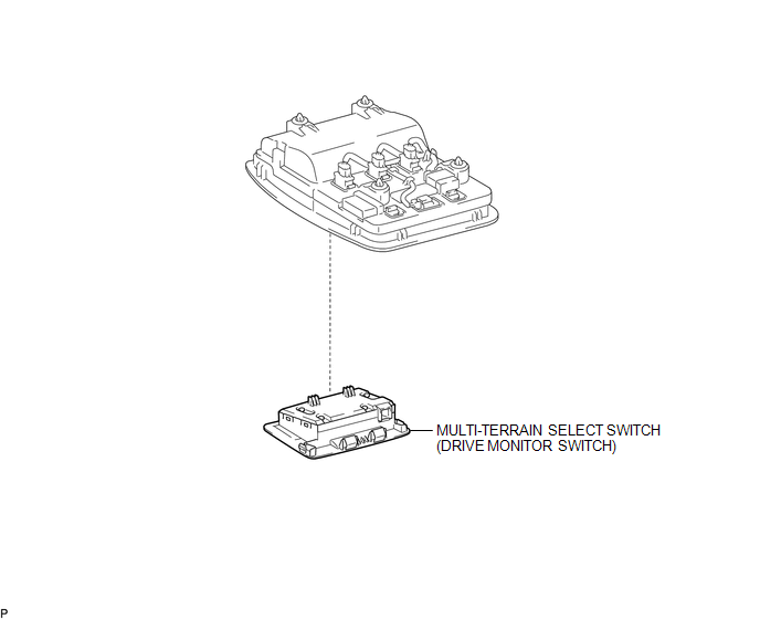
1. REMOVE MULTI-TERRAIN SELECT SWITCH (DRIVE MONITOR SWITCH)
|
(a) Disengage the 2 claws to remove the multi-terrain select switch (drive monitor switch). |
|
.png)
Inspection
INSPECTION
PROCEDURE
1. INSPECT MULTI-TERRAIN SELECT SWITCH (DRIVE MONITOR SWITCH)
(a) Check the resistance.
(1) Measure the resistance according to the value(s) in the table below.
 Text in Illustration
|
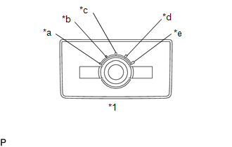
*1 |
Multi-terrain Select Switch |
|
*a |
MUD and SAND |
|
*b |
LOOSE ROCK |
|
*c |
MOGUL |
|
*d |
ROCK and DIRT |
|
*e |
ROCK |
 Text in Illustration
|
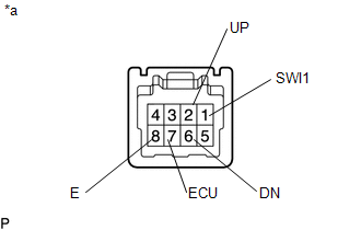
*a |
Component without harness connected (Multi-terrain Select Switch (Drive Monitor Switch)) |
Standard Resistance:
|
Tester Connection |
Switch Condition |
Specified Condition |
|---|---|---|
|
7 (ECU) - 8 (E) |
MUD and SAND |
Below 1 Ω |
|
2 (UP) - 8 (E) |
||
|
6 (DN) - 8 (E) |
10 kΩ or higher |
|
|
7 (ECU) - 8 (E) |
LOOSE ROCK |
Below 1 Ω |
|
2 (UP) - 8 (E) |
10 kΩ or higher |
|
|
6 (DN) - 8 (E) |
||
|
7 (ECU) -8 (E) |
MOGUL |
10 kΩ or higher |
|
2 (UP) -8 (E) |
||
|
6 (DN) -8 (E) |
||
|
7 (ECU) - 8 (E) |
ROCK and DIRT |
10 kΩ or higher |
|
2 (UP) - 8 (E) |
||
|
6 (DN) - 8 (E) |
Below 1 Ω |
|
|
7 (ECU) - 8 (E) |
ROCK |
10 kΩ or higher |
|
2 (UP) - 8 (E) |
Below 1 Ω |
|
|
6 (DN) - 8 (E) |
||
|
1 (SWl1) - 8 (E) |
ON/OFF: Pressed |
Below 1 Ω |
|
ON/OFF: Not pressed |
10 kΩ or higher |
If the result is not as specified, replace the multi-terrain select switch (drive monitor switch).
Installation
INSTALLATION
PROCEDURE
1. INSTALL MULTI-TERRAIN SELECT SWITCH (DRIVE MONITOR SWITCH)
(a) Engage the 2 claws to install the multi-terrain select switch (drive monitor switch).
 Front Speed Sensor
Removal
REMOVAL
PROCEDURE
1. PRECAUTION
NOTICE:
After turning the ignition switch off, waiting time may be required before disconnecting
the cable from the negative (-) battery terminal.
The ...
 Rear Speed Sensor
Removal
REMOVAL
PROCEDURE
1. PRECAUTION
NOTICE:
After turning the ignition switch off, waiting time may be required before disconnecting
the cable from the negative (-) battery terminal.
The ...
Other materials:
Lost Communication with ECM / PCM "A" (U0100,U0129,U0142,U0151,U0163,U023A,U1104)
DESCRIPTION
The combination meter communicates with the ECM, skid control ECU, power steering
ECU, main body ECU (multiplex network body ECU), airbag sensor assembly, navigation
receiver assembly*1, radio and display receiver assembly*2, Forward recognition
camera*3 and Millimeter wave radar ...
Taillight Relay Circuit
DESCRIPTION
The main body ECU (multiplex network body ECU) controls the operation of the
TAIL relay.
WIRING DIAGRAM
CAUTION / NOTICE / HINT
NOTICE:
Inspect the fuses for circuits related to this system before performing
the following inspection procedure.
If the main body EC ...
Disassembly
DISASSEMBLY
CAUTION / NOTICE / HINT
HINT:
Use the same procedure for both the LH and RH sides.
The procedure described below is for the LH side.
PROCEDURE
1. REMOVE NO. 1 HEADLIGHT BULB
(a) Turn the No. 1 headlight bulb in the direction indicated by the arrow
i ...
