Toyota Tacoma (2015-2018) Service Manual: On-vehicle Inspection
ON-VEHICLE INSPECTION
PROCEDURE
1. INSPECT FRONT SEAT AIRBAG ASSEMBLY LH (for Vehicle not Involved in Collision)
|
(a) Perform a diagnostic system check (See page
|
|
.gif) ).
).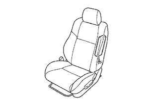
(b) With the front seat airbag assembly LH installed on the vehicle, perform a visual check. If there are any defects as mentioned below, replace the front seat with a new one:
Cuts, minute cracks or marked discoloration on the front seatback around the front seat airbag assembly LH.
2. INSPECT FRONT SEAT AIRBAG ASSEMBLY LH (for Vehicle Involved in Collision and Airbag has not Deployed)
|
(a) Perform a diagnostic system check (See page
|
|
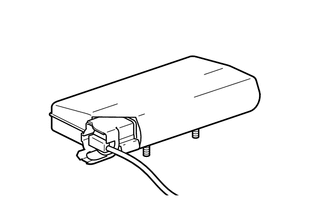
(b) With the front seat airbag assembly LH removed from the vehicle, perform a visual check. If there are any defects as mentioned below, replace the front seat airbag assembly LH with a new one:
- Cuts, minute cracks or marked discoloration on the front seat airbag assembly LH.
- Cracks or other damage to the wire harness or connector.
CAUTION:
For removal and installation procedures of the front seat airbag assembly LH, be sure to follow the correct procedure.
 Installation
INSTALLATION
CAUTION / NOTICE / HINT
CAUTION:
Wear protective gloves. Sharp areas on the parts may injure your hands.
HINT:
Use the same procedure for both the RH and LH sides.
The pr ...
 Removal
REMOVAL
CAUTION / NOTICE / HINT
CAUTION:
Be sure to read Precaution thoroughly before servicing (See page
).
If the side airbag was deployed, replace the front seat airbag assembly ...
Other materials:
Automatic High Beam System does not Operate or Operation Indicator does not
Illuminate
DESCRIPTION
The main body ECU (multiplex network body ECU) controls the automatic high beam
system based on signals received from the forward recognition camera.
WIRING DIAGRAM
CAUTION / NOTICE / HINT
NOTICE:
When replacing the combination meter assembly, always replace it with
...
Inspection
INSPECTION
PROCEDURE
1. INSPECT AUTO HIGH BEAM SWITCH
*a
Component without harness connected
(Auto High Beam Switch)
(a) Check the resistance.
(1) Measure the resistance according to the value(s) in the table below.
Standard Resistance:
Tester C ...
How To Proceed With Troubleshooting
CAUTION / NOTICE / HINT
HINT:
Perform the following procedure to troubleshoot the dynamic radar cruise
control system.
*: Use the Techstream.
PROCEDURE
1.
VEHICLE BROUGHT TO WORKSHOP
NEXT
...
