Toyota Tacoma (2015-2018) Service Manual: Removal
REMOVAL
PROCEDURE
1. REMOVE WATER INLET WITH THERMOSTAT SUB-ASSEMBLY
(See page .gif) )
)
2. REMOVE NO. 1 RADIATOR HOSE
3. REMOVE NO. 2 RADIATOR HOSE
4. DISCONNECT RADIATOR RESERVE TANK HOSE
5. SEPARATE TRANSMISSION OIL COOLER HOSE (for Automatic Transmission)
|
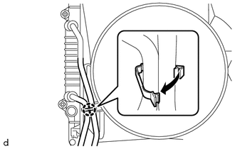
(a) Disengage the clamp to separate the 2 transmission oil cooler hoses from the fan shroud. |
|
6. REMOVE FAN SHROUD
7. REMOVE COOLER COMPRESSOR ASSEMBLY
(See page )
8. REMOVE V-RIBBED BELT TENSIONER ASSEMBLY
9. SEPARATE VANE PUMP ASSEMBLY
|
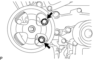
(a) Remove the 2 bolts and separate the vane pump assembly from the timing chain cover assembly. |
|
10. REMOVE NO. 2 IDLER PULLEY SUB-ASSEMBLY
|
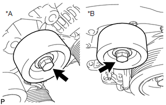
(a) Remove the 2 bolts and 2 No. 2 idler pulley sub-assemblies from the timing chain cover assembly. Text in Illustration
|
|
11. REMOVE ENGINE WATER PUMP ASSEMBLY
|
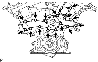
(a) Remove the 15 bolts, engine water pump assembly and gasket from the timing chain cover assembly. |
|
 On-vehicle Inspection
ON-VEHICLE INSPECTION
PROCEDURE
1. INSPECT FOR COOLANT LEAK
HINT:
The sliding surface inside the engine water pump assembly is lubricated
by engine coolant. As some engine coolant is d ...
 Installation
INSTALLATION
PROCEDURE
1. INSTALL ENGINE WATER PUMP ASSEMBLY
(a) Install the engine water pump assembly and a new gasket to the timing
chain cover assembly with the 15 bolts.
Torq ...
Other materials:
Remote Control System does not Operate
DESCRIPTION
The main body ECU (multiplex network body ECU) receives remote control signals
from the driver door key cylinder or wireless transmitter. Then, the main body ECU
(multiplex network body ECU) sends the remote control signals to the sliding roof
ECU (sliding roof drive gear sub-asse ...
Combination Meter ECU Communication Stop Mode
DESCRIPTION
Detection Item
Symptom
Trouble Area
Combination Meter ECU Communication Stop Mode
Either condition is met:
Communication stop for "Combination Meter" is indicated on the
"Communication Bus Ch ...
Precaution
PRECAUTION
PRECAUTION FOR DISCONNECTING CABLE FROM NEGATIVE BATTERY TERMINAL
NOTICE:
When disconnecting the cable from the negative (-) battery terminal,
initialize the following systems after the cable is reconnected.
Click here
If the battery has been discharged and char ...
