Toyota Tacoma (2015-2018) Service Manual: Disposal
DISPOSAL
PROCEDURE
1. DISPOSE OF BRAKE BOOSTER ACCUMULATOR ASSEMBLY
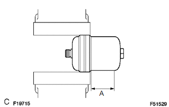
(a) Place the brake booster accumulator in a vise and cover it with a cloth.
(b) Slowly cut a hole on the brake booster accumulator side in the A portion shown in the illustration on the left. And discharge the gas and liquid inside.
NOTICE:
- As gas may spray out, cover the brake booster accumulator with a cloth when performing the operation.
- Work slowly and do not cut the hole too quickly or suddenly.
- Wear protective glasses during the operation.
(c) When the outer body of the brake booster accumulator is cut, gas and liquid discharge.
HINT:
- The gas is colorless, odorless and nonpoisonous nitrogen gas.
- The liquid is brake fluid.
 Reassembly
REASSEMBLY
PROCEDURE
1. INSTALL BRAKE BOOSTER ACCUMULATOR ASSEMBLY
(a) Place the brake booster pump in a vise with a cloth.
(b) Install the brake booster accumulator pipe, compression spring and ...
 Installation
INSTALLATION
PROCEDURE
1. INSTALL HYDRAULIC BRAKE BOOSTER
(a) Install a new brake booster gasket onto the hydraulic brake booster.
(b) Install the hydraulic brake booster with the 4 nuts.
Torque: ...
Other materials:
Road Test
ROAD TEST
PROBLEM SYMPTOM CONFIRMATION
HINT:
The dynamic radar cruise control system has 2 cruise control modes:
constant speed control mode and vehicle-to-vehicle distance control mode.
Vehicle-to-vehicle distance control mode is selected by default when
the dyna ...
Reassembly
REASSEMBLY
PROCEDURE
1. INSTALL COMPRESSOR PICK UP SENSOR
(a) Install the compressor pick up sensor with the 3 screws.
(b) Engage the clamp.
2. INSTALL MAGNET CLUTCH ASSEMBLY
(a) Secure the cooler compressor assembly in a vise between ...
Rear Center Seat Outer Belt Assembly(for Double Cab)
Components
COMPONENTS
ILLUSTRATION
Removal
REMOVAL
PROCEDURE
1. REMOVE REAR SEATBACK HINGE COVER
2. REMOVE REAR SEATBACK BOARD SUB-ASSEMBLY
3. REMOVE SEAT BELT ANCHOR COVER CAP
4. REMOVE REAR SEAT SHOULDER BELT COVER
5. REMOVE CENTER SEATBACK PAD
(a) Remove th ...
