Toyota Tacoma (2015-2018) Service Manual: Installation
INSTALLATION
PROCEDURE
1. INSTALL HYDRAULIC BRAKE BOOSTER
(a) Install a new brake booster gasket onto the hydraulic brake booster.
(b) Install the hydraulic brake booster with the 4 nuts.
Torque:
14 N·m {145 kgf·cm, 10 ft·lbf}
|
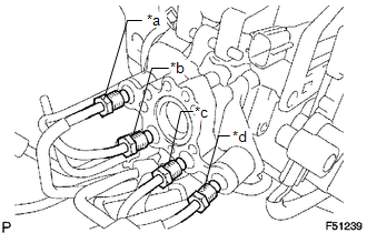
(c) Using a union nut wrench, connect the 4 brake lines to the correct positions of the hydraulic brake booster, as shown in the illustration. Text in Illustration
Torque: without union nut wrench : 15 N·m {155 kgf·cm, 11 ft·lbf} with union nut wrench : 14 N·m {145 kgf·cm, 10 ft·lbf} HINT:
|
|
(d) Connect the 3 connectors.
2. INSTALL MASTER CYLINDER PUSH ROD CLEVIS
.gif)
3. INSTALL LOWER NO. 1 INSTRUMENT PANEL AIRBAG ASSEMBLY
(See page )
4. INSPECT BRAKE PEDAL HEIGHT
5. INSPECT PEDAL FREE PLAY
6. INSPECT PEDAL RESERVE DISTANCE
7. FILL RESERVOIR WITH BRAKE FLUID
8. BLEED BRAKE BOOSTER WITH ACCUMULATOR PUMP ASSEMBLY
9. BLEED BRAKE LINE
10. BLEED MASTER CYLINDER SOLENOID
11. INSPECT FLUID LEVEL IN RESERVOIR
12. INSPECT FOR BRAKE FLUID LEAK
13. INSPECT BRAKE MASTER CYLINDER OPERATION
 Disposal
DISPOSAL
PROCEDURE
1. DISPOSE OF BRAKE BOOSTER ACCUMULATOR ASSEMBLY
(a) Place the brake booster accumulator in a vise and cover it with a cloth.
(b) Slowly cut a hole on the brake booster accumu ...
 Rear Brake
...
Other materials:
Multi-terrain Select Indicator Light Remains ON
DESCRIPTION
Refer to Multi-terrain Select Indicator Light does not Come ON (See page
).
WIRING DIAGRAM
CAUTION / NOTICE / HINT
NOTICE:
When replacing the skid control ECU (master cylinder solenoid), perform
calibration (See page
).
Inspect the fuses for circuits related ...
Pressure Control Solenoid "D" Performance (Shift Solenoid Valve SLT) (P2714)
SYSTEM DESCRIPTION
The shift solenoid valve SLT controls the transmission line pressure for smooth
transmission operation based on signals from the throttle position sensor and the
vehicle speed sensor. The ECM adjusts the current to shift solenoid valve SLT to
control hydraulic line pressure ...
Customize Parameters
CUSTOMIZE PARAMETERS
PROCEDURE
1. CUSTOMIZE WIRELESS DOOR LOCK CONTROL SYSTEM (w/ Smart Key System)
HINT:
The following items can be customized.
NOTICE:
When the customer requests a change in a function, first make sure that
the function can be customized.
Be sure to make a not ...
