Toyota Tacoma (2015-2018) Service Manual: Lost Communication with Meter (B1324)
DESCRIPTION
This DTC is stored when a communication error occurs between the navigation receiver assembly and combination meter assembly.
|
DTC No. |
DTC Detection Condition |
Trouble Area |
|---|---|---|
|
B1324 |
After the navigation receiver assembly receives a registration information signal, which is sent by the combination meter assembly when the ignition switch is ACC, 1 or more times, the navigation receiver assembly cannot receive the signal for 30 seconds or more. |
|
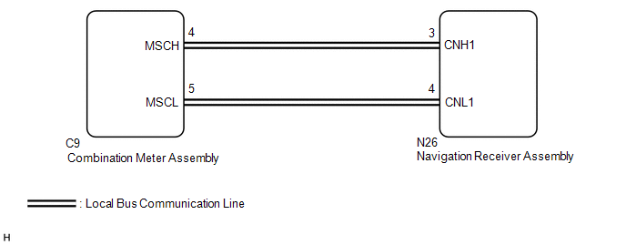
WIRING DIAGRAM
PROCEDURE
|
1. |
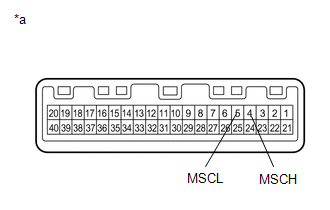
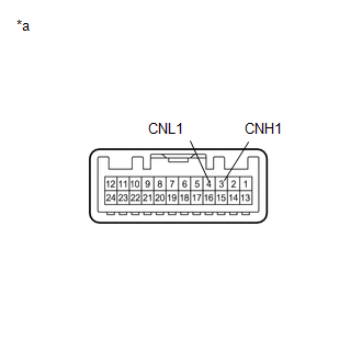
CHECK HARNESS AND CONNECTOR (NAVIGATION RECEIVER ASSEMBLY - COMBINATION METER ASSEMBLY) |
(a) Disconnect the N26 navigation receiver assembly connector.
(b) Disconnect the C9 combination meter assembly connector.
(c) Measure the resistance according to the value(s) in the table below.
Standard Resistance:
|
Tester Connection |
Condition |
Specified Condition |
|---|---|---|
|
N26-3 (CNH1) - C9-4 (MSCH) |
Always |
Below 1 Ω |
|
N26-4 (CNL1) - C9-5 (MSCL) |
Always |
Below 1 Ω |
|
N26-3 (CNH1) - Body ground |
Always |
10 kΩ or higher |
|
N26-4 (CNL1) - Body ground |
Always |
10 kΩ or higher |
|
N26-3 (CNH1) - N26-4 (CNL1) |
Always |
10 kΩ or higher |
(d) Measure the voltage according to the value(s) in the table below.
Standard Voltage:
|
Tester Connection |
Condition |
Specified Condition |
|---|---|---|
|
N26-3 (CNH1) - Body ground |
Always |
Below 1 V |
|
N26-4 (CNL1) - Body ground |
Always |
Below 1 V |
| NG | .gif) |
REPAIR OR REPLACE HARNESS OR CONNECTOR |
|
.gif)
|
2. |
INSPECT COMBINATION METER ASSEMBLY |
(a) Remove the combination meter assembly (See page
.gif) ).
).
|
(b) Measure the resistance according to the value(s) in the table below. Standard Resistance:
|
|
| NG | |
REPLACE COMBINATION METER ASSEMBLY |
|
|
3. |
INSPECT NAVIGATION RECEIVER ASSEMBLY |
(a) Remove the navigation receiver assembly (See page
).
|
(b) Measure the resistance according to the value(s) in the table below. Standard Resistance:
|
|
| NG | |
REPLACE NAVIGATION RECEIVER ASSEMBLY |
|
|
4. |
REPLACE COMBINATION METER ASSEMBLY |
(a) Replace the combination meter assembly with a new or known good one (See
page ).
(b) Clear the DTCs (See page ).
(c) Recheck for DTCs and check that no DTCs are output.
OK:
No DTCs are output.
| NG | |
REPLACE NAVIGATION RECEIVER ASSEMBLY |
|
|
5. |
CHECK METER / GAUGE SYSTEM |
(a) Turn the ignition switch to ON and wait 30 seconds.
(b) Operate the steering pad switch assembly and check that the audio tab is displayed on the multi-information display in the combination meter assembly and the audio system can be operated normally.
OK:
Audio system returns to normal.
| OK | |
END |
| NG | |
REPLACE NAVIGATION RECEIVER ASSEMBLY |
 Diagnostic Trouble Code Chart
DIAGNOSTIC TROUBLE CODE CHART
Navigation System
DTC Code
Detection Item
See page
B1324
Lost Communication with Meter
...
 LVDS Signal Malfunction (from Extension Module) (B1532,B156C)
DESCRIPTION
DTC Code
DTC Detection Condition
Trouble Area
B1532
When one of the conditions below is met:
Video signal (digit ...
Other materials:
Installation
INSTALLATION
CAUTION / NOTICE / HINT
HINT:
Use the same procedure for the RH and LH sides.
The procedure described below is for the LH side.
PROCEDURE
1. REPAIR INSTRUCTION
(a) Clean the vehicle body surface.
(1) Using a heat light, heat the vehicle body surface.
Heating Te ...
Removal
REMOVAL
PROCEDURE
1. REMOVE ROOF HEADLINING ASSEMBLY (for LED Type Stop Light)
for Double Cab:
(See page
)
for Access Cab:
(See page
)
2. REMOVE CENTER STOP LIGHT ASSEMBLY (for Bulb Type Stop Light)
(a) Apply protective tape around the center stop light as ...
Reassembly
REASSEMBLY
PROCEDURE
1. INSTALL FRONT AXLE HUB OIL SEAL
(a) Using a brass bar and a hammer, install a new front axle hub oil seal.
NOTICE:
Do not damage the oil seal.
2. INSTALL FRONT AXLE WITH ABS ROTOR BEARING ASSEMBLY
(a) Using SST and a press, install a new bearing onto the front axle ...
