Toyota Tacoma (2015-2018) Service Manual: Clutch Switch Circuit
DESCRIPTION
Clutch switch circuit inspection is necessary for manual transmission vehicles.
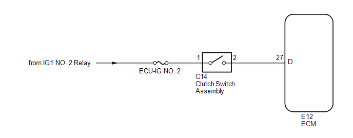
When the clutch pedal is released, the ECM receives the positive (+) battery voltage through the ECU-IG NO. 2 fuse and ignition switch. While the clutch pedal is depressed, the clutch switch assembly sends a signal to terminal D of the ECM. The ECM cancels cruise control when terminal D receives the signal (voltage of below 1 V).
WIRING DIAGRAM
CAUTION / NOTICE / HINT
NOTICE:
Inspect the fuses for circuits related to this system before performing the following inspection procedure.
PROCEDURE
|
1. |
CHECK HARNESS AND CONNECTOR (ECM - BATTERY) |
(a) Disconnect the ECM connector.
(b) Turn the ignition switch to the ON position.
(c) Measure the voltage according to the value(s) in the table below.
Standard Voltage:
|
Tester Connection |
Condition |
Specified Condition |
|---|---|---|
|
E12-27 (D) - Body ground |
Clutch pedal depressed |
Below 1 V |
|
E12-27 (D) - Body ground |
Clutch pedal released |
11 to 14 V |
|
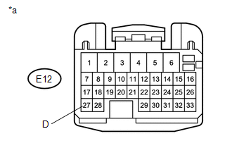
*a |
Front view of wire harness connector (to ECM) |
(d) Reconnect the ECM connector.
| OK | .gif) |
PROCEED TO PROCEED TO NEXT SUSPECTED AREA SHOWN IN PROBLEM SYMPTOMS TABLE |
|
.gif)
|
2. |
INSPECT CLUTCH SWITCH ASSEMBLY |
|
(a) Remove the clutch switch assembly (See page
|
|
.gif)
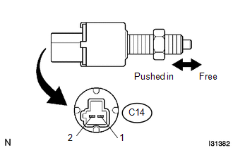
(b) Measure the resistance according to the value(s) in the table below.
Standard Resistance:
|
Tester Connection |
Condition |
Specified Condition |
|---|---|---|
|
C14-1 - C14-2 |
Clutch pedal depressed |
10 kΩ or higher |
|
C14-1 - C14-2 |
Clutch pedal released |
Below 1 Ω |
(c) Reinstall the clutch switch.
| NG | |
REPLACE CLUTCH SWITCH ASSEMBLY |
|
|
3. |
CHECK HARNESS AND CONNECTOR (CLUTCH SWITCH ASSEMBLY - ECM) |
(a) Disconnect the E12 ECM connector.
(b) Disconnect the C14 clutch switch assembly connector.
(c) Measure the resistance according to the value(s) in the table below.
Standard Resistance:
|
Tester Connection |
Condition |
Specified Condition |
|---|---|---|
|
C14-2 - Body ground |
Always |
10 kΩ or higher |
|
C14-2 - E12-27 (D) |
Always |
Below 1 Ω |
(d) Reconnect the clutch switch connector.
(e) Reconnect the ECM connector.
| OK | |
REPAIR OR REPLACE HARNESS OR CONNECTOR (CLUTCH SWITCH ASSEMBLY - BATTERY) |
| NG | |
REPAIR OR REPLACE HARNESS OR CONNECTOR (CLUTCH SWITCH ASSEMBLY - ECM) |
 Brake System (P157800)
DESCRIPTION
This DTC is output when the VSC system has a problem. Check the VSC system when
this DTC is output.
DTC No.
DTC Detection Condition
Trouble Area
...
 Brake Switch "A" Signal Compare Failure (P057162)
DESCRIPTION
When the brake pedal is depressed, stop light switch assembly sends a signal
to the ECM. Upon receiving the signal, the ECM cancels the cruise control system.
DTC Code
...
Other materials:
If your vehicle overheats
The following may indicate that your vehicle is overheating.
● The needle of the engine coolant temperature gauge (→P. 155) enters the red
zone or a loss of engine power is experienced.
(For example, the vehicle speed does not increase.) ● Steam comes out from under
the hood. ...
IG Signal Circuit
DESCRIPTION
This circuit detects whether the ignition switch is ON or off, and sends this
information to the main body ECU (multiplex network body ECU).
WIRING DIAGRAM
CAUTION / NOTICE / HINT
NOTICE:
Inspect the fuses for circuits related to this system before performing
the fol ...
Main Owners Manual
Please note that this manual applies to all models explains and all equipment,
including options. Therefore, you may find some explanations for equipment not installed
on your vehicle.
All specifications provided in this manual are current at the time of printing.
However, because of the Toyot ...
