Toyota Tacoma (2015-2018) Service Manual: Reassembly
REASSEMBLY
PROCEDURE
1. INSTALL BRAKE BOOSTER ACCUMULATOR ASSEMBLY
.png)
(a) Place the brake booster pump in a vise with a cloth.
(b) Install the brake booster accumulator pipe, compression spring and a new O-ring.
NOTICE:
Ensure that no foreign matter enters the pump.
(c) Using a socket wrench (17 mm), install the brake booster accumulator onto the brake booster pump.
Torque:
57 N·m {585 kgf·cm, 42 ft·lbf}
2. INSTALL MASTER CYLINDER SOLENOID
.png)
(a) Place a new gasket on the master cylinder solenoid and install them onto the master cylinder body with 6 new bolts.
Torque:
32 N·m {325 kgf·cm, 24 ft·lbf}
NOTICE:
Do not let water, dust, and/or other objects attach to the surface and/or attaching surface of the master cylinder solenoid, master cylinder and body gasket.
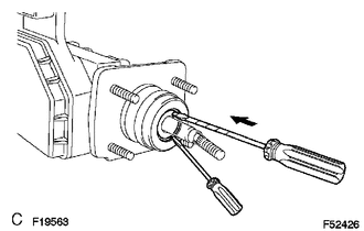
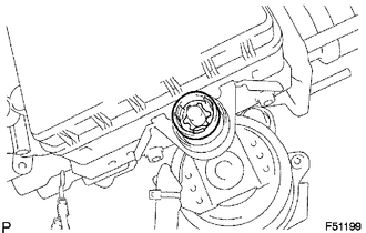
3. INSTALL PISTON
(a) Apply lithium soap base glycol grease to the new piston.
(b) Install the piston onto the master cylinder body.
|
(c) Using 2 screwdrivers, install a new C-ring while pressing the piston. NOTICE:
|
|
4. INSTALL MASTER CYLINDER BOOT
5. INSTALL MASTER CYLINDER PUSH ROD CLEVIS
(a) Install the lock nut and master cylinder push rod clevis onto the rod operating adapter.
(b) Install the hydraulic brake booster side lock nut and rod operating adapter onto the hydraulic brake booster.
Torque:
26 N·m {260 kgf·cm, 19 ft·lbf}
6. INSTALL BRAKE BOOSTER PUMP BRACKET
.png)
(a) Using a hexagon wrench (5 mm), install the brake booster pump bracket with the 2 screws.
Torque:
7.8 N·m {80 kgf·cm, 69 in·lbf}
(b) Install the bush onto the brake booster pump bracket.
7. INSTALL BRAKE ACTUATOR BRACKET
.png)
(a) Using a hexagon wrench (5 mm), install the brake actuator bracket with the screw.
Torque:
7.8 N·m {80 kgf·cm, 69 in·lbf}
8. INSTALL BRAKE BOOSTER WITH ACCUMULATOR PUMP ASSEMBLY
.png)
(a) Install the 2 collars and 2 bushes onto the brake booster w/ accumulator pump assembly.
(b) Using a hexagon wrench (4 mm), install the 2 pins.
Torque:
7.8 N·m {80 kgf·cm, 69 in·lbf}
|
(c) Install the brake booster w/ accumulator pump assembly. |
|
.png)
|
(d) Install a new clip. |
|
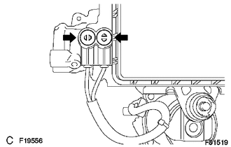
|
(e) Install the wire harness with the 2 screws. Torque: 2.9 N·m {30 kgf·cm, 26 in·lbf} |
|
|
(f) Install the 2 new plugs. |
|
9. INSTALL BRAKE ACTUATOR TUBE NO. 1
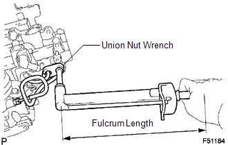
(a) Using a union nut wrench, install the brake actuator tube No. 1.
Torque:
without union nut wrench :
15 N·m {155 kgf·cm, 11 ft·lbf}
with union nut wrench :
14 N·m {145 kgf·cm, 10 ft·lbf}
HINT:
- This torque value can be obtained by using a torque wrench with a fulcrum
length of 300 mm (11.8 in.) and a union nut wrench with a fulcrum length
of 22 mm (0.866 in.) (See page
.gif) ).
). - This torque value is effective when the union nut wrench is parallel to the torque wrench.
10. INSTALL BRAKE ACTUATOR HOSE NO.1
.png)
(a) Using needle-nose pliers, install the brake actuator hose and 2 clips.
11. INSTALL BRAKE MASTER CYLINDER RESERVOIR SUB-ASSEMBLY
(a) Install the cap.
(b) Apply lithium soap base glycol grease to the 3 new grommets.
(c) Install the 3 grommets to the master cylinder body.
NOTICE:
Be careful of the size of each grommets.
(d) Install the master cylinder reservoir.
|
(e) Using a pin punch and hammer, install a new pin onto the master cylinder reservoir. |
|
.png)
|
(f) Install the screw onto the master cylinder reservoir. Torque: 1.7 N·m {17 kgf·cm, 15 in·lbf} |
|
.png)
12. INSTALL BRAKE ACTUATOR BRACKET NO. 1
.png)
(a) Install the fluid level warning switch connector.
(b) Using a hexagon wrench (5 mm), install the brake actuator bracket No. 1 with the screw.
Torque:
7.8 N·m {80 kgf·cm, 69 in·lbf}
 Inspection
INSPECTION
PROCEDURE
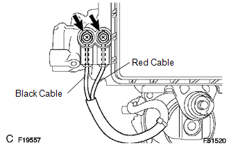
1. INSPECT BRAKE BOOSTER PUMP ASSEMBLY
(a) Connect the positive (+) lead from the battery to the red cable of the pump,
and the negative (-) lead to the black cable.
(b) C ...
 Disposal
DISPOSAL
PROCEDURE
1. DISPOSE OF BRAKE BOOSTER ACCUMULATOR ASSEMBLY
(a) Place the brake booster accumulator in a vise and cover it with a cloth.
(b) Slowly cut a hole on the brake booster accumu ...
Other materials:
Freeze Frame Data
FREEZE FRAME DATA
1. FREEZE FRAME DATA
(a) Whenever a meter DTC is detected, the combination meter assembly stores the
current vehicle state as freeze frame data.
2. CHECK FREEZE FRAME DATA
(a) Connect the Techstream to the DLC3.
(b) Turn the ignition switch to ON.
(c) Turn the Techstream on ...
Precaution
PRECAUTION
1. INITIALIZATION
NOTICE:
If the ECM is replaced, register the ECU communication ID for Engine
Immobiliser System (See page ).
Perform Registration (VIN registration) when replacing the ECM (See
page ).
HINT:
The engine learned value cannot be rese ...
Customize Parameters
CUSTOMIZE PARAMETERS
NOTICE:
When the customer requests a change in a function, first make sure that
the function can be customized.
Make a note of the current settings before customizing.
HINT:
The following PCS functions and the pre-collision system sensitivity setting
...
