Toyota Tacoma (2015-2018) Service Manual: Disassembly
DISASSEMBLY
PROCEDURE
1. REMOVE TELEPHONE MICROPHONE ASSEMBLY
Click here .gif)
2. REMOVE MICROPHONE CASE
HINT:
Use the same procedure for Double Cab.
Click here
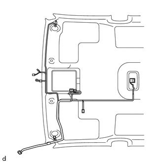
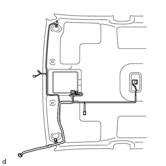
3. REMOVE NO. 1 ROOF WIRE (w/ Vanity Light)
|
(a) w/ EC Mirror: (1) Remove the No. 1 roof wire. |
|
|
(b) w/o EC Mirror: (1) Remove the No. 1 roof wire. |
|
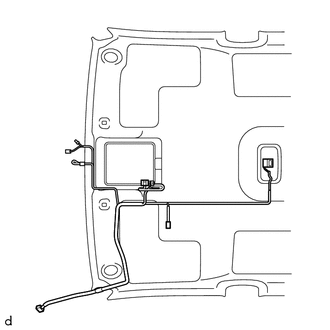
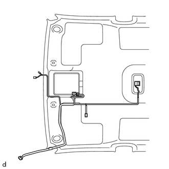
4. REMOVE NO. 1 ROOF WIRE (w/o Vanity Light)
|
(a) w/ EC Mirror: (1) Remove the No. 1 roof wire. |
|
|
(b) w/o EC Mirror: (1) Remove the No. 1 roof wire. |
|
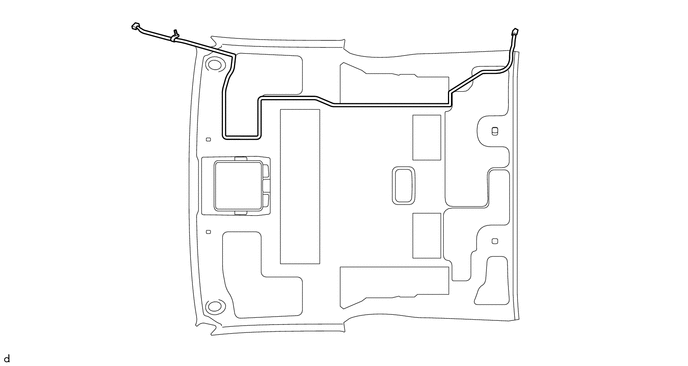
5. REMOVE NO. 2 ANTENNA CORD SUB-ASSEMBLY
(a) Remove the No. 2 antenna cord sub-assembly.
 Components
COMPONENTS
ILLUSTRATION
*A
w/ Rear Seat Assembly
*B
w/o Rear Seat Assembly
*1
BACK PANEL GARNISH HOLE PLUG
*2
...
 Installation
INSTALLATION
PROCEDURE
1. INSTALL ROOF HEADLINING ASSEMBLY
(a) Insert the roof headlining assembly into the vehicle from the door.
NOTICE:
Check that the corners of th ...
Other materials:
Ecm
Components
COMPONENTS
ILLUSTRATION
ILLUSTRATION
Installation
INSTALLATION
PROCEDURE
1. INSTALL NO. 2 ECM BRACKET
(a) Install the No. 2 ECM bracket to the ECM with the 2 screws.
Torque:
3.2 N·m {33 kgf·cm, 28 in·lbf}
2. INSTALL ECM BRACKET
(a) Install the ECM bracket to the EC ...
Main Switch Illumination Circuit
DESCRIPTION
When the light control switch is turned to the tail or head position, this circuit
sends an illumination signal to the wireless charger main switch (mobile wireless
charger switch). Based on this signal, the wireless charger main switch (mobile
wireless charger switch) is illumina ...
Transfer Case Rear Oil Seal
Components
COMPONENTS
ILLUSTRATION
Replacement
REPLACEMENT
PROCEDURE
1. DRAIN TRANSFER OIL
2. REMOVE PROPELLER WITH CENTER BEARING SHAFT ASSEMBLY
(See page )
3. REMOVE OUTPUT SHAFT COMPANION FLANGE SUB-ASSEMBLY
4. REMOVE TRANSFER EXTENSION HOUSING TYPE T OIL SEAL
( ...
