Toyota Tacoma (2015-2018) Service Manual: Reassembly
REASSEMBLY
CAUTION / NOTICE / HINT
HINT:
- Use the same procedures for both the LH and RH sides.
- The procedure described below is for the LH side.
PROCEDURE
1. INSTALL SIDE TURN SIGNAL LIGHT ASSEMBLY (w/ Side Turn Signal Light)
.gif)
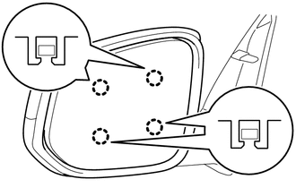
2. INSTALL OUTER MIRROR COVER (w/o Side Turn Signal Light)
|
(a) Engage the 8 claws to install the outer mirror cover. |
|
.png)
3. INSTALL OUTER MIRROR COVER (w/ Side Turn Signal Light)
|
(a) Engage the 7 claws to install the outer mirror cover. |
|
.png)
4. INSTALL OUTER MIRROR
|
(a) Connect the 3 connectors. |
|
.png)
(b) Engage the clamp.
|
(c) Engage the 4 claws to install the outer mirror. NOTICE: Be careful not to press the outer mirror with excessive force to prevent the glass from breaking. |
|
 Inspection
INSPECTION
PROCEDURE
1. INSPECT OUTER MIRROR LH
(a) Check the outer mirror heater operation.
Text in Illustration
*a
Component without harness con ...
 Installation
INSTALLATION
CAUTION / NOTICE / HINT
HINT:
Use the same procedures for both the LH and RH sides.
The procedure described below is for the LH side.
PROCEDURE
1. INSTALL OUTER REA ...
Other materials:
System Diagram
SYSTEM DIAGRAM
...
Distance Control Switch Circuit
DESCRIPTION
The distance control switch is used to set the distance for vehicle-to-vehicle
distance control mode. The distance control switch is installed in the steering
pad switch assembly. The vehicle-to-vehicle distance set value can be changed by
operating the steering pad switch assembl ...
Steering Angle Sensor Initialization Incomplete (C1439,C1445)
DESCRIPTION
The skid control ECU (master cylinder solenoid) acquires steering angle sensor
(spiral cable with sensor sub-assembly) zero point every time the ignition switch
is turned to ON and the vehicle is driven at 35 km/h (22 mph) or more for approximately
5 seconds. The ECU also stores t ...
