Toyota Tacoma (2015-2018) Service Manual: Installation
INSTALLATION
PROCEDURE
1. INSTALL ROOF HEADLINING ASSEMBLY
|
(a) Insert the roof headlining assembly into the vehicle from the door. NOTICE:
|
|
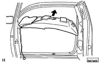
(b) Install the roof headlining assembly.
(c) Engage the clamp.
(d) w/ EC Mirror:
(1) Connect the connector.
(e) Connect the 2 connectors.
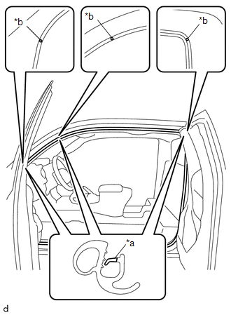
(f) for Front pillar LH side:
(1) Connect the 2 connectors.
(2) Engage the clamp and guide.
(g) for Front pillar RH side:
(1) Connect the connector.
(2) Engage the clamp.
(3) Engage the guide and install the bolt.
(h) for Rear pillar RH side:
(1) Connect the connector.
(2) Engage the clamp.
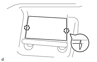
2. INSTALL NO. 1 FORWARD RECOGNITION COVER
Click here .gif)
3. INSTALL COAT HOOK
Click here
4. INSTALL VISOR HOLDER LH
Click here
5. INSTALL VISOR HOLDER RH
HINT:
Use the same procedure as for the LH side.
6. INSTALL VISOR ASSEMBLY LH (w/ Vanity Light)
Click here
7. INSTALL VISOR ASSEMBLY RH (w/ Vanity Light)
HINT:
Use the same procedure as for the LH side.
8. INSTALL VISOR ASSEMBLY LH (w/o Vanity Light)
Click here
9. INSTALL VISOR ASSEMBLY RH (w/o Vanity Light)
HINT:
Use the same procedure as for the LH side.
10. INSTALL ASSIST GRIP PLUG
HINT:
Use the same procedures as for the opposite side.
(a) Engage the clip to install the assist grip plug.
(b) Install the cover.
11. INSTALL ROOF CONSOLE BOX ASSEMBLY
Click here
12. INSTALL NO. 1 ROOM LIGHT ASSEMBLY
Click here
13. INSTALL INNER REAR VIEW MIRROR COVER (w/ EC Mirror)
Click here
14. INSTALL QUARTER TRIM INSIDE BOARD LH
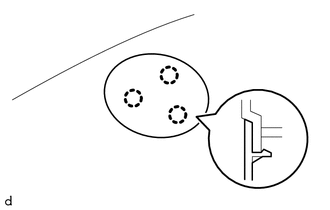
(a) Engage the 3 clips to install the quarter trim inside board LH.
(b) Install the bolt.
|
(c) Engage the 3 claws to close the cover. |
|
15. INSTALL QUARTER TRIM INSIDE BOARD RH
HINT:
Use the same procedure as for the LH side.
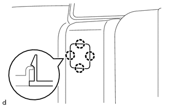
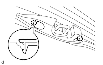
16. INSTALL ROOF SIDE INNER GARNISH LH
(a) Engage the guide, clip and 3 claws to install the roof side inner garnish LH.
17. INSTALL ROOF SIDE INNER GARNISH RH
HINT:
Use the same procedure as for the LH side.
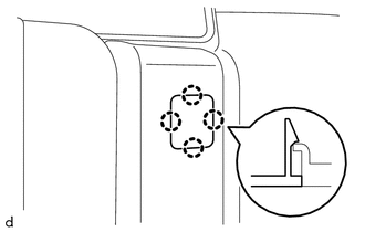
18. INSTALL QUARTER TRIM LOWER PANEL LH
(a) Engage the 2 clips and 2 claws to install the quarter trim lower panel LH.
19. INSTALL QUARTER TRIM LOWER PANEL RH
HINT:
Use the same procedure as for the LH side.
20. CONNECT REAR SEAT 3 POINT TYPE OUTER BELT ASSEMBLY LH
(a) Connect the rear seat 3 point type outer belt assembly LH with the bolt.
Torque:
42 N·m {428 kgf·cm, 31 ft·lbf}
21. CONNECT REAR SEAT 3 POINT TYPE OUTER BELT ASSEMBLY RH
HINT:
Use the same procedure as for the LH side.
22. INSTALL BACK PANEL TRIM (w/ Rear Seat Assembly)
(a) for RH side:
(1) Engage the 8 clips and 5 claws to install the back panel trim.
(2) Install the bolt.
Torque:
5.5 N·m {56 kgf·cm, 49 in·lbf}
(b) for LH side:
(1) Engage the 6 clips and 10 claws to install the back panel trim.
(2) Install the 2 bolts.
Torque:
5.5 N·m {56 kgf·cm, 49 in·lbf}
23. INSTALL BACK PANEL TRIM (w/o Rear Seat Assembly)
(a) Engage the 14 clips and 10 claws to install the back panel trim.
24. INSTALL NO. 3 ROOM PARTITION COVER (w/ Rear Seat Assembly)
|
(a) Engage the 4 claws to install the No. 3 room partition cover. |
|
25. INSTALL NO. 4 ROOM PARTITION COVER LH (w/ Rear Seat Assembly)
|
(a) Engage the 4 claws to install the No. 4 room partition cover LH. |
|
26. INSTALL NO. 4 ROOM PARTITION COVER RH (w/ Rear Seat Assembly)
HINT:
Use the same procedure as for the LH side.
27. INSTALL BACK PANEL GARNISH HOLE PLUG
HINT:
Use the same procedure, install every back panel garnish hole plug.
|
(a) Engage the 2 claws to install the back panel garnish hole plug. |
|
28. INSTALL REAR SEAT CUSHION ASSEMBLY
Click here
29. INSTALL FRONT PILLAR GARNISH LH
Click here
30. INSTALL FRONT PILLAR GARNISH RH
Click here
31. INSTALL ASSIST GRIP SUB-ASSEMBLY
Click here
32. INSTALL FRONT DOOR OPENING TRIM WEATHERSTRIP LH
|
(a) Align the paint mark on the front door opening trim weatherstrip LH with the mark position on the vehicle and install the front door opening trim weatherstrip LH as shown in the illustration.
Paint Mark:
NOTICE:
HINT: To easily install the weatherstrip, first install the area with the paint mark as shown in the illustration. Then install the part to ward the corners and push any excess length into the corners. |
|
33. INSTALL FRONT DOOR OPENING TRIM WEATHERSTRIP RH
HINT:
Use the same procedure as for the LH side.
34. INSTALL ROOF SIDE INNER GARNISH CAP LH
(a) Engage the 4 claws to install the roof side inner garnish cap LH.
(b) Using a T30 "TORX" socket wrench, install the 2 screws.
|
(c) Engage the 2 claws to close the 2 covers. |
|
35. INSTALL ROOF SIDE INNER GARNISH CAP RH
HINT:
Use the same procedure as for the LH side.
36. INSTALL REAR DOOR SCUFF PLATE LH
(a) Engage the guide, clip and 8 claws to install the rear door scuff plate LH.
37. INSTALL REAR DOOR SCUFF PLATE RH
HINT:
Use the same procedure as for the LH side.
38. INSTALL COWL SIDE TRIM BOARD LH
Click here
39. INSTALL COWL SIDE TRIM BOARD RH
HINT:
Use the same procedure as for the LH side.
40. INSTALL FRONT DOOR SCUFF PLATE LH
(a) Engage the guide and 11 claws to install the front door scuff plate LH.
41. INSTALL FRONT DOOR SCUFF PLATE RH
HINT:
Use the same procedure as for the LH side.
 Disassembly
DISASSEMBLY
PROCEDURE
1. REMOVE TELEPHONE MICROPHONE ASSEMBLY
Click here
2. REMOVE MICROPHONE CASE
HINT:
Use the same procedure for Double Cab.
Click here
3. REMOVE NO. 1 ROOF WIRE (w/ Van ...
 Reassembly
REASSEMBLY
PROCEDURE
1. INSTALL NO. 2 ANTENNA CORD SUB-ASSEMBLY
(a) Using hot-melt glue, install the No. 2 antenna cord sub-assembly as shown
in the illustration.
2. INSTALL NO. 1 ROOF WIRE (w ...
Other materials:
Reservoir Level Switch Disconnected (C1453,C1454)
DESCRIPTION
The brake fluid level warning switch sends the appropriate signal to the skid
control ECU (master cylinder solenoid) when the brake fluid level drops.
DTC Code
DTC Detection Condition
Trouble Area
C1453
With the ECU termina ...
Inspection
INSPECTION
PROCEDURE
1. INSPECT NO. 1 ULTRASONIC SENSOR
(a) Measure the resistance according to the value(s) in the table below.
Text in Illustration
*a
Component without harness connected:
(No. 1 Ultrasonic Sensor)
Standar ...
Installation
INSTALLATION
PROCEDURE
1. INSTALL REAR AXLE SHAFT OIL SEAL
(a) Using SST and a hammer, install a new oil seal.
SST: 09950-60020
09951-00770
SST: 09950-70010
09951-07150
2. INSTALL REAR AXLE SHAFT WITH BACKING PLATE
(a) Install a new O-ring.
(b) Install the rear axle shaft with backing ...
