Toyota Tacoma (2015-2018) Service Manual: Components
COMPONENTS
ILLUSTRATION
|
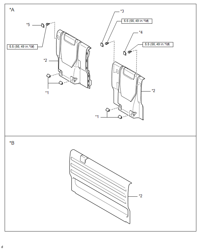
*A |
w/ Rear Seat Assembly |
*B |
w/o Rear Seat Assembly |
|
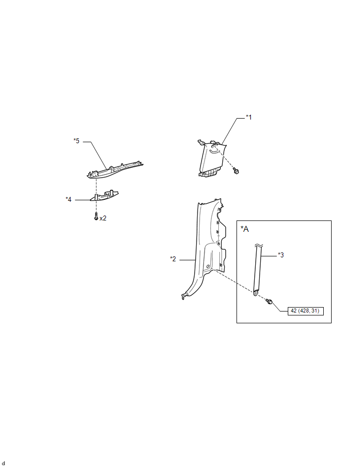
*1 |
BACK PANEL GARNISH HOLE PLUG |
*2 |
BACK PANEL TRIM |
|
*3 |
NO. 3 ROOM PARTITION COVER |
*4 |
NO. 4 ROOM PARTITION COVER LH |
|
*5 |
NO. 4 ROOM PARTITION COVER RH |
- |
- |
.png) |
N*m (kgf*cm, ft.*lbf): Specified torque |
- |
- |
ILLUSTRATION
|
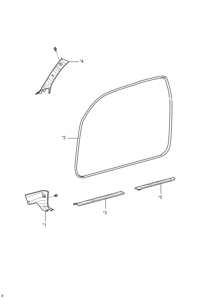
*1 |
COWL SIDE TRIM BOARD LH |
*2 |
FRONT DOOR OPENING TRIM WEATHERSTRIP LH |
|
*3 |
FRONT DOOR SCUFF PLATE LH |
*4 |
FRONT PILLAR GARNISH LH |
|
*5 |
REAR DOOR SCUFF PLATE LH |
- |
- |
ILLUSTRATION
|
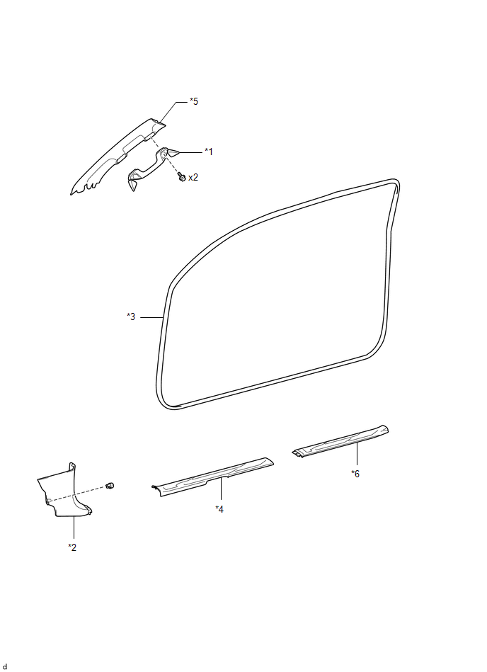
*1 |
ASSIST GRIP SUB-ASSEMBLY |
*2 |
COWL SIDE TRIM BOARD RH |
|
*3 |
FRONT DOOR OPENING TRIM WEATHERSTRIP RH |
*4 |
FRONT DOOR SCUFF PLATE RH |
|
*5 |
FRONT PILLAR GARNISH RH |
*6 |
REAR DOOR SCUFF PLATE RH |
ILLUSTRATION
|
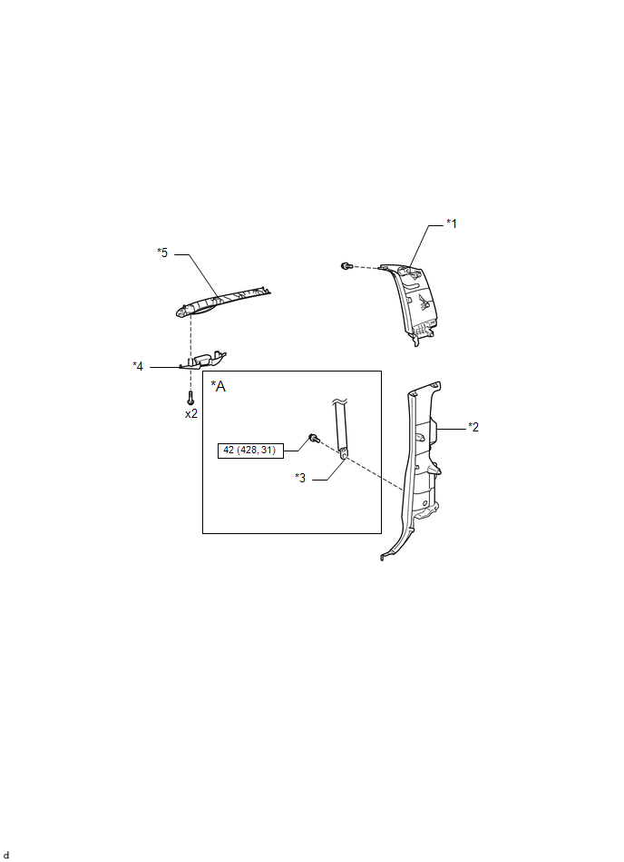
*A |
w/ Rear Seat Assembly |
- |
- |
|
*1 |
QUARTER TRIM INSIDE BOARD LH |
*2 |
QUARTER TRIM LOWER PANEL LH |
|
*3 |
REAR SEAT 3 POINT TYPE OUTER BELT ASSEMBLY LH |
*4 |
ROOF SIDE INNER GARNISH CAP LH |
|
*5 |
ROOF SIDE INNER GARNISH LH |
- |
- |
|
|
N*m (kgf*cm, ft.*lbf): Specified torque |
- |
- |
ILLUSTRATION
|
*A |
w/ Rear Seat Assembly |
- |
- |
|
*1 |
QUARTER TRIM INSIDE BOARD RH |
*2 |
QUARTER TRIM LOWER PANEL RH |
|
*3 |
REAR SEAT 3 POINT TYPE OUTER BELT ASSEMBLY RH |
*4 |
ROOF SIDE INNER GARNISH CAP RH |
|
*5 |
ROOF SIDE INNER GARNISH RH |
- |
- |
|
|
N*m (kgf*cm, ft.*lbf): Specified torque |
- |
- |
ILLUSTRATION
|
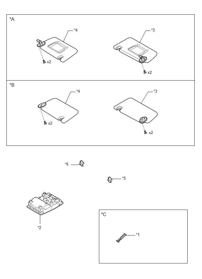
*A |
w/ Vanity Light |
*B |
w/o Vanity Light |
|
*C |
w/ EC Mirror |
- |
- |
|
*1 |
INNER REAR VIEW MIRROR COVER |
*2 |
ROOF CONSOLE BOX ASSEMBLY |
|
*3 |
VISOR ASSEMBLY LH |
*4 |
VISOR ASSEMBLY RH |
|
*5 |
VISOR HOLDER LH |
*6 |
VISOR HOLDER RH |
ILLUSTRATION
|
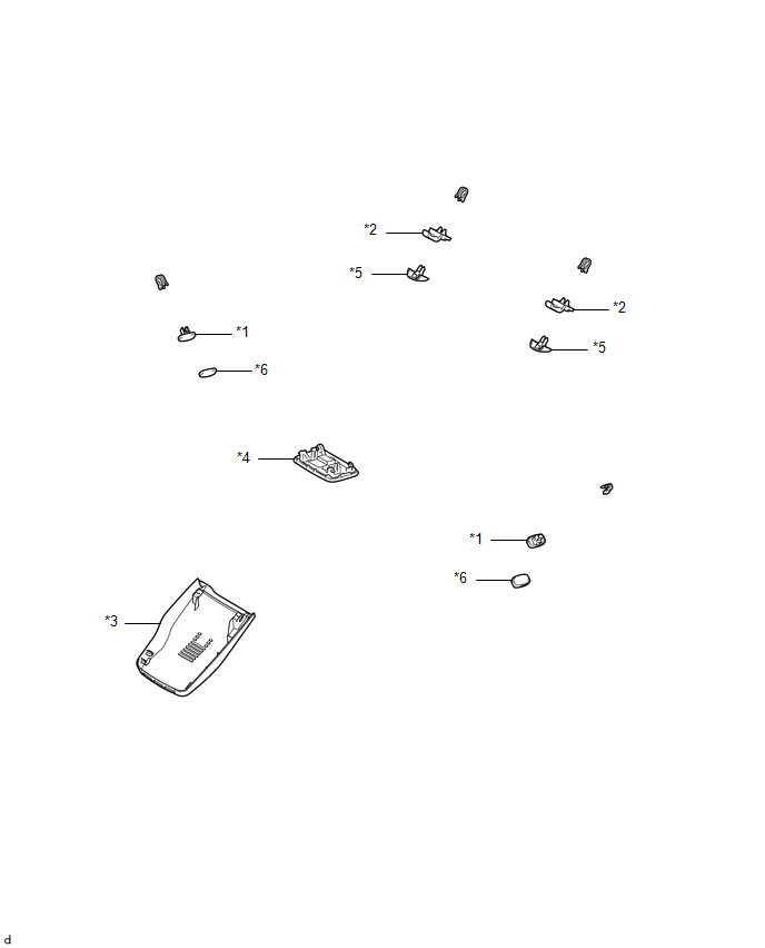
*1 |
ASSIST GRIP PLUG |
*2 |
COAT HOOK |
|
*3 |
NO. 1 FORWARD RECOGNITION COVER |
*4 |
NO. 1 ROOM LIGHT ASSEMBLY |
|
*5 |
COVER |
*6 |
ASSIST GRIP COVER |
ILLUSTRATION
|
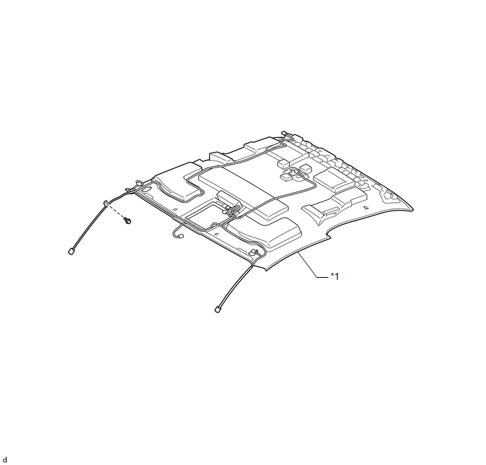
*1 |
ROOF HEADLINING ASSEMBLY |
- |
- |
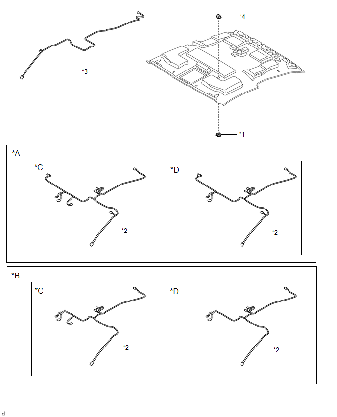
ILLUSTRATION
|
*A |
w/ Vanity Light |
*B |
w/o Vanity Light |
|
*C |
w/ EC Mirror |
*D |
w/o EC Mirror |
|
*1 |
MICROPHONE CASE |
*2 |
NO. 1 ROOF WIRE |
|
*3 |
NO. 2 ANTENNA CORD SUB-ASSEMBLY |
*4 |
TELEPHONE MICROPHONE ASSEMBLY |

 Disassembly
DISASSEMBLY
PROCEDURE
1. REMOVE TELEPHONE MICROPHONE ASSEMBLY
Click here
2. REMOVE MICROPHONE CASE
HINT:
Use the same procedure for Double Cab.
Click here
3. REMOVE NO. 1 ROOF WIRE (w/ Van ...
Other materials:
Air Inlet Damper Position Sensor Circuit (B1432/32)
DESCRIPTION
This sensor detects the position of the air inlet damper and sends the appropriate
signals to the air conditioning amplifier assembly. The position sensor is built
into the No. 1 air conditioning servo assembly (fresh/recirculation damper).
DTC No.
DTC Detecti ...
Customize Parameters
CUSTOMIZE PARAMETERS
1. CUSTOMIZE SMART KEY SYSTEM (for Entry Function)
HINT:
The following items can be customized.
NOTICE:
When the customer requests a change in a function, first make sure that
the function can be customized.
Record the current settings before customizing.
...
Problem Symptoms Table
PROBLEM SYMPTOMS TABLE
HINT:
Use the table below to help determine the cause of problem symptoms. If multiple
suspected areas are listed, the potential causes of the symptoms are listed in order
of probability in the "Suspected Area" column of the table. Check each symptom by
check ...
