Toyota Tacoma (2015-2018) Service Manual: Diagnosis System
DIAGNOSIS SYSTEM
DIAGNOSIS FUNCTION
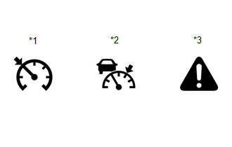
(a) The diagnosis function turns off the cruise control indicator, illuminates the master warning light and displays a warning message when a malfunction is detected. When a malfunction is detected in the dynamic radar cruise control system, DTCs are stored in the ECM or millimeter wave radar sensor assembly.
|
*1 |
Cruise Control Indicator (Constant Speed Control Mode) |
|
*2 |
Cruise Control Indicator (Vehicle-to-vehicle Distance Control Mode) |
|
*3 |
Master Warning Light |
NOTICE:
- If DTCs related to the communication system are stored, "Cruise Control Malfunction Visit Your Dealer", which is displayed in the combination meter assembly, disappears when the system returns to normal.
- If DTCs not related to the communication system are stored, "Cruise Control Malfunction Visit Your Dealer", which is displayed in the combination meter assembly, disappears when the ignition switch off then back ON after the system returns to normal.
DESCRIPTION
(a) The ECM and millimeter wave radar sensor assembly control the dynamic radar cruise control system of the vehicle. The data and DTCs relating to the dynamic radar cruise control system can be read from the DLC3 of the vehicle. Use the Techstream to check and solve the problem.
CHECK DLC3
(a) Check the DLC3.
Click here .gif)
CHECK INDICATOR
(a) Turn the ignition switch to ON.
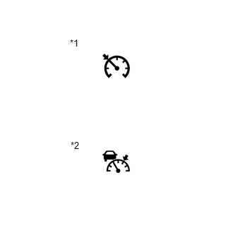
(b) Check that the cruise control indicator illuminates when the dynamic radar cruise control system is turned on using the cruise control main switch (ON-OFF button), and that the indicator turns off when the dynamic radar cruise control system is turned off using the cruise control main switch (ON-OFF button).
|
*1 |
Cruise Control Indicator (Constant Speed Control Mode) |
|
*2 |
Cruise Control Indicator (Vehicle-to-vehicle Distance Control Mode) |
 Road Test
ROAD TEST
PROBLEM SYMPTOM CONFIRMATION
HINT:
The dynamic radar cruise control system has 2 cruise control modes:
constant speed control mode and vehicle-to-vehicle distance control mode ...
 Problem Symptoms Table
PROBLEM SYMPTOMS TABLE
NOTICE:
Before replacing the ECM, refer to Registration.
w/o Smart Key System: Click here
w/ Smart Key System: Click here
When the millimeter wave rad ...
Other materials:
Utility
UTILITY
NOTICE:
If the forward recognition camera has been replaced due to a malfunction in the
lane departure alert system, be sure to perform Recognition Camera/Target Position
Memory and Optical Axis Learning. Otherwise all systems that use the forward recognition
camera may be affected.
...
Invalid Data Received from Deceleration Sensor (C1442,C1443)
DESCRIPTION
The airbag sensor assembly has a built-in yaw rate and acceleration sensor.
The skid control ECU (brake actuator assembly) receives signals from the yaw
rate and acceleration sensor (airbag sensor assembly) via the CAN communication
system.
DTC No.
Detection ...
General maintenance
Listed below are the general maintenance items that should be performed at
the intervals specified in the ÔÇťScheduled Maintenance GuideÔÇŁ or ÔÇťOwnerÔÇÖs Manual
SupplementÔÇŁ. It is recommended that any problem you notice should be brought to
the attention of your Toyota dealer or qualified ...
