Toyota Tacoma (2015-2018) Service Manual: Open in Bus 5 Main Bus Line
DESCRIPTION
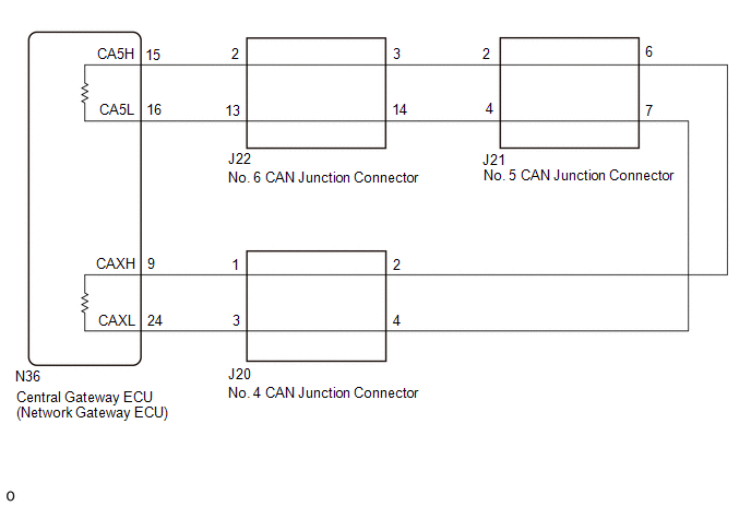
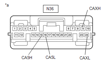
There may be an open circuit in one of the CAN main bus lines when the resistance between terminals 15 (CA5H) and 16 (CA5L) of the central gateway ECU (network gateway ECU) is 70 Ω or higher.
|
Detection Item |
Trouble Area |
|---|---|
|
Resistance between terminals 15 (CA5H) and 16 (CA5L) of central gateway ECU (network gateway ECU) is 70 Ω or higher. |
|
This malfunction is not related to the lines of a CAN branch or to ECUs or sensors connected to a CAN branch.
WIRING DIAGRAM
CAUTION / NOTICE / HINT
CAUTION:
When performing the confirmation driving pattern, obey all speed limits and traffic laws.
NOTICE:
- Because the order of diagnosis is important to allow correct diagnosis,
make sure to begin troubleshooting using How to Proceed with Troubleshooting
when CAN communication system related DTCs are output.
Click here
.gif)
- Before measuring the resistance of the CAN bus, turn the ignition switch off and leave the vehicle for 1 minute or more without operating the key or any switches, or opening or closing the doors. After that, disconnect the cable from the negative (-) battery terminal and leave the vehicle for 1 minute or more before measuring the resistance.
- After turning the ignition switch off, waiting time may be required
before disconnecting the cable from the negative (-) battery terminal. Therefore,
make sure to read the disconnecting the cable from the negative (-) battery
terminal notices before proceeding with work.
Click here
- Some parts must be initialized and set when replacing or removing and
installing parts.
Click here
- After performing repairs, perform the DTC check procedure and confirm
that the DTCs are not output again.
DTC check procedure: Turn the ignition switch to ON and wait for 1 minute or more. Then operate the suspected malfunctioning system and drive the vehicle at 60 km/h (37 mph) or more for 5 minutes or more.
- After the repair, perform the CAN bus check and check that all the ECUs
and sensors connected to the CAN communication system are displayed as normal.
Click here
HINT:
- Before disconnecting related connectors for inspection, push in on each connector body to check that the connector is not loose or disconnected.
- When a connector is disconnected, check that the terminals and connector body are not cracked, deformed or corroded.
PROCEDURE
|
1. |
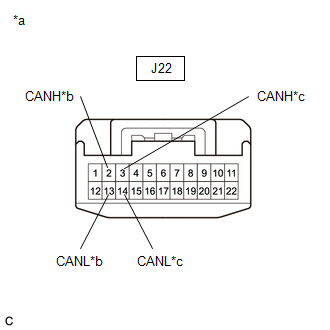
CHECK FOR OPEN IN CAN BUS WIRE (NO. 6 CAN JUNCTION CONNECTOR) |
(a) Disconnect the cable from the negative (-) battery terminal.
(b) Disconnect the No. 6 CAN junction connector.
|
(c) Measure the resistance according to the value(s) in the table below. Standard Resistance:
|
|
|
Result |
Proceed to |
|---|---|
|
OK |
A |
|
NG (Central gateway ECU (network gateway ECU) CAN main line) |
B |
|
NG (No. 2 CAN junction connector CAN main line) |
C |
| A | .gif) |
REPLACE NO. 6 CAN JUNCTION CONNECTOR |
| C | |
GO TO STEP 3 |
|
.gif)
|
2. |
CHECK FOR OPEN IN CAN MAIN BUS LINES (CENTRAL GATEWAY ECU (NETWORK GATEWAY ECU) - NO. 6 CAN JUNCTION CONNECTOR) |
(a) Reconnect the J22 No. 6 CAN junction connector.
(b) Disconnect the central gateway ECU (network gateway ECU) connector.
|
(c) Measure the resistance according to the value(s) in the table below. Standard Resistance:
|
|
| OK | |
REPLACE CENTRAL GATEWAY ECU (NETWORK GATEWAY ECU) |
| NG | |
REPAIR OR REPLACE CAN MAIN WIRE OR CONNECTOR (CENTRAL GATEWAY ECU (NETWORK GATEWAY ECU) - NO. 6 CAN JUNCTION CONNECTOR) |
|
3. |
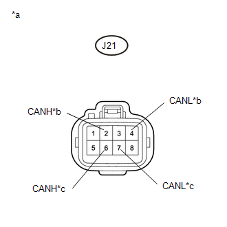
CHECK FOR OPEN IN CAN MAIN BUS LINES (NO. 5 CAN JUNCTION CONNECTOR) |
(a) Reconnect the J22 No. 6 CAN junction connector.
(b) Disconnect the No. 5 CAN junction connector.
|
(c) Measure the resistance according to the value(s) in the table below. Standard Resistance:
|
|
|
Result |
Proceed to |
|---|---|
|
OK |
A |
|
NG (No. 6 CAN junction connector CAN main line) |
B |
|
NG (No. 4 CAN junction connector CAN main line) |
C |
| A | |
REPLACE NO. 5 CAN JUNCTION TERMINAL |
| B | |
REPAIR OR REPLACE CAN MAIN WIRE OR CONNECTOR (NO. 5 CAN JUNCTION CONNECTOR - NO. 6 CAN JUNCTION CONNECTOR) |
|
|
4. |
CHECK FOR OPEN IN CAN MAIN BUS LINES (NO. 4 CAN JUNCTION CONNECTOR) |
(a) Reconnect the J21 No. 5 CAN junction connector.
(b) Disconnect the No. 4 CAN junction connector.
|
(c) Measure the resistance according to the value(s) in the table below. Standard Resistance:
|
|
|
Result |
Proceed to |
|---|---|
|
OK |
A |
|
NG (No. 5 CAN junction connector CAN main line) |
B |
|
NG (Central gateway ECU (network gateway ECU) CAN main line) |
C |
| A | |
REPLACE NO. 4 CAN JUNCTION CONNECTOR |
| B | |
REPAIR OR REPLACE CAN MAIN WIRE OR CONNECTOR (NO. 4 CAN JUNCTION CONNECTOR - NO. 5 CAN JUNCTION TERMINAL) |
|
|
5. |
CHECK FOR OPEN IN CAN MAIN BUS LINES (CENTRAL GATEWAY ECU (NETWORK GATEWAY ECU) - NO. 4 CAN JUNCTION CONNECTOR) |
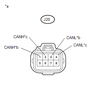
(a) Reconnect the J20 No. 4 CAN junction connector.
(b) Disconnect the central gateway ECU (network gateway ECU) connector.
|
(c) Measure the resistance according to the value(s) in the table below. Standard Resistance:
|
|
| OK | |
REPLACE CENTRAL GATEWAY ECU (NETWORK GATEWAY ECU) |
| NG | |
REPAIR OR REPLACE CAN MAIN BUS LINES OR CONNECTOR (CENTRAL GATEWAY ECU (NETWORK GATEWAY ECU) - NO. 4 CAN JUNCTION CONNECTOR) |
 Check Bus 3 Line for Short to GND
DESCRIPTION
There may be a short circuit between one of the CAN bus lines and GND when there
is no resistance between terminal 6 (CA3H) of the central gateway ECU (network gateway
ECU) and termin ...
 Open in One Side of Bus 3 Branch Line
DESCRIPTION
When the CAN bus main lines are normal (no open, short to ground, short to +B
or short between lines) and there is an ECU or sensor on the "Communication Bus
Check" screen t ...
Other materials:
Removal
REMOVAL
PROCEDURE
1. PRECAUTION
NOTICE:
After turning the ignition switch off, waiting time may be required before disconnecting
the cable from the negative (-) battery terminal. Therefore, make sure to read the
disconnecting the cable from the negative (-) battery terminal notices before pr ...
Using the radio
Select “AM” or “FM” on the “Select Audio Source” screen to begin listening
to the radio.
Audio control screen
“Select Audio Source” screen
appears
Preset stations
Select to display RBDS text
message
Scanning for receivable station
Sele ...
Precaution
PRECAUTION
1. EXPRESSIONS OF IGNITION SWITCH
HINT:
The type of ignition switch used on this model differs according to the specifications
of the vehicle. The expressions listed in the table below are used in this section.
Expression
Ignition Switch
(Position)
...
